Description
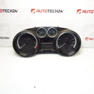
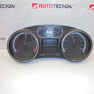
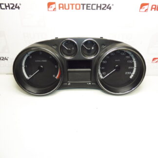
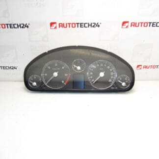
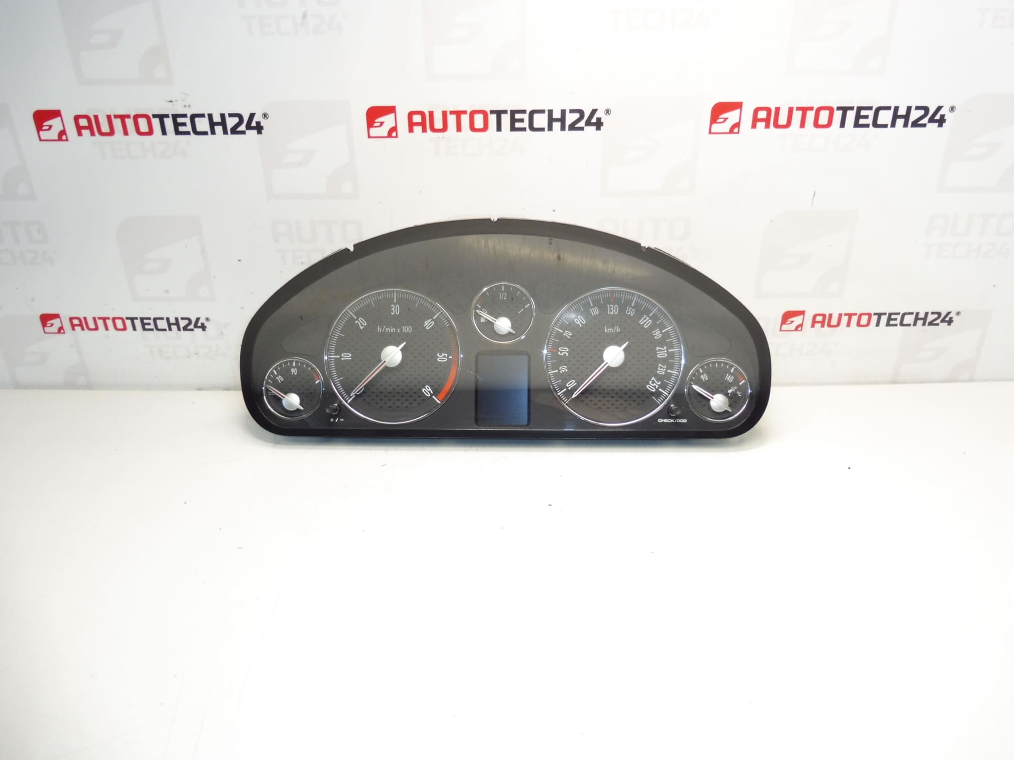
Instrument cluster tachometer dashboard Peugeot 407 2.0 HDi 2008. Mileage approx. 280000 km. Display works OK.
Product Overview
This instrument cluster (tachometer and dashboard assembly) is intended for Peugeot 407 vehicles and is suitable for professional mechanics and experienced DIY enthusiasts. The unit includes analogue gauges with a central LCD odometer and status indicators. Commonly searched by OE part numbers, this cluster is a direct-fit replacement for vehicles using the listed references and is ideal when the original cluster shows mileage, display or gauge issues.
Technical Information
- Manufacturer: Stellantis (Citroën/Peugeot)
- Model: Peugeot 407 2.0 HDi (2008)
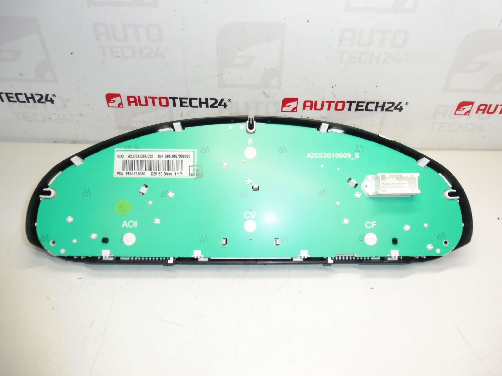
- Product Codes: 9654815080, 9664690380
- Other Numbers: 610395, 610396
Compatibility And Application
Designed for Peugeot 407 models equipped with the 2.0 HDi powerplant and corresponding electrical architecture. Compatibility is typically determined by matching OE part numbers (9654815080, 9664690380, 610395, 610396). Useful for replacing faulty clusters that exhibit faulty gauges, partial or damaged LCD segments, or erratic readings.
Installation Recommendations
- Disconnect the negative battery terminal before beginning work to avoid short circuits and preserve vehicle electronics.
- Remove trim panels surrounding the steering column and dashboard to access the cluster retaining screws.
- Carefully unscrew the cluster, slide it forward, and unplug the electrical connectors—avoid pulling on wires.
- Transfer any necessary bezel clips or odometer lenses if required, then fit the replacement cluster in reverse order.
- After reconnecting the battery, verify all warning lights, indicators, backlighting and the odometer display. Some vehicles may require coding or calibration for immobilizer or mileage alignment; arrange programming if dash warnings persist.
Common Failure Causes
Instrument clusters of this age and mileage typically fail due to a combination of factors: gradual LCD or backlight degradation, worn stepper motors driving the needles, corrosion or poor contacts at connectors, cracked solder joints from thermal cycling and vibration, and intermittent faults from moisture ingress. High mileage units are more prone to faded illumination and missing segments on the digital display.
Why Choose This Unit
This cluster shows approximately 280,000 km and a functioning display, making it a practical replacement option for workshops and competent home mechanics looking to restore dashboard functionality quickly. Listing of OE numbers in the technical data helps searches and ensures a better chance of correct fitment.