Description
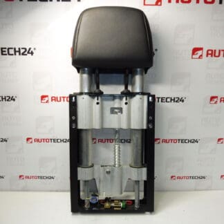
Rear headrest activation unit for PEUGEOT 307 CC cars up to 2004
Part description
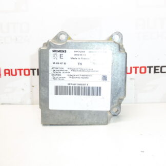
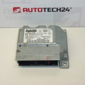
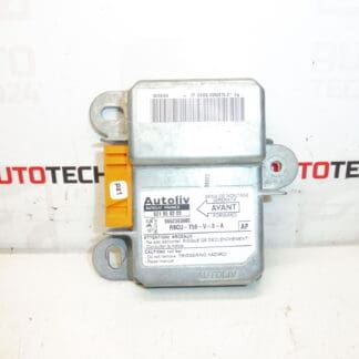
The part for sale is a used rear headrest activation unit intended for Peugeot 307 CC. It is an electronic module from the category of control units, which is mainly searched by part number – that’s why we include all available codes from the label in the description. A suitable solution when replacing the original unit after a defect or when repairing the wiring related to the function of activating the backrest.
Technical information
- Manufacturer: Stellantis Citroën Peugeot
- Model: Peugeot 307 CC (up to 2004)
- Other numbers: RBCU-T56-V-2-A, NFP
Product codes
- Product codes: 9652363880, 6010958200, 8852L2, 8852L3
Installation recommendations
Generally/typically for electronic control modules, the exact procedure may vary by car design and wiring. Below is a practical, safe procedure for replacing this type of unit without specifying specific values.
1) Before assembly (checks of used part)
- Compare all part numbers on the label (9652363880, 6010958200, 8852L2/8852L3) to the old unit.
- Check for damage to connectors, pins or unit body (cracks, signs of moisture/oxidation).
- Verify that the type designation from the label matches (e.g. RBCU-T56-V-2-A), if the original part also has it.
2) Necessary tools and materials
- Basic set of bits/keys and screwdrivers according to the used connecting material
- Plastic pry bar for removing covers/trimming (if needed)
- Flashlight
- Contact cleaner for electrical connectors (optional)
3) Step-by-step assembly procedure
- Turn off the ignition and secure the vehicle against movement.
- Disconnect the battery (for electronic units, this is essential to prevent short circuits and damage).
- Get access to the unit (remove any necessary covers/panelling to avoid damaging the mounts).
- Take a photo of the wiring and wiring for proper re-seating.
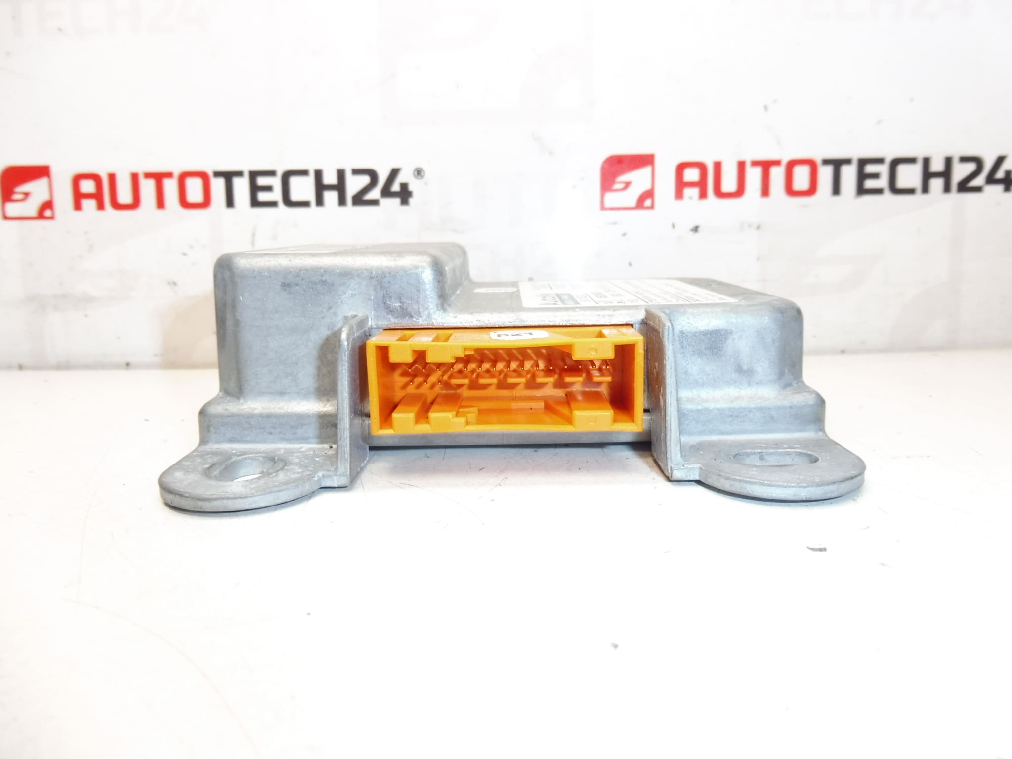
- Remove the connectors carefully – do the unlocking without prying “by force” so as not to break the fuses.
- Remove the original unit from the bracket/mount.
- Compare the old and new piece (codes, connectors, mounting) before installation.
- Mount the unit in its original mount and seat it properly.
- Connect the connectors – they must be fully engaged and secured with fuses.
- Check the cable routing for tension, sharp edges, or pinching by the cover.
- Refit the covers/trims in the reverse order of removal.
- Connect the battery.
-
4) Post-assembly checks and function verification
- Check for an unusual message/fault related to that circuit when the ignition is turned on.
- Verify the function of the system to which the unit belongs (headrest activation) according to the capabilities of the specific car.
- If contamination/oxidation of the connectors has been detected, it is recommended to check the stability of the contact with slight movement of the wiring (without force) after assembly.
5) The most common assembly mistakes + how to avoid them
- Battery not disconnected → risk of short circuit and damage to the unit; always disconnect before handling the connectors.
- Replacing the unit according to a similar number → always verify all codes and markings listed.
- Incorrectly clicked connector → malfunctions occur; connectors must be fully secured by a fuse.
- Pinched wiring when mounting the covers → subsequent interruption of wires; check everything visually before tightening.
Reasons why the part is damaged
- Moisture and contact corrosion in the connectors or where the unit is stored.
- Damage to cabling (pinched, frayed, broken wires) leading to unstable power/signal.
- Overvoltage or short circuit in the electrical system (e.g. during improper handling without disconnecting the battery).
- Mechanical damage to connectors/pins during disassembly and assembly.
- Electronics age and heat stress, which can lead to solder joint failures over time.