Description
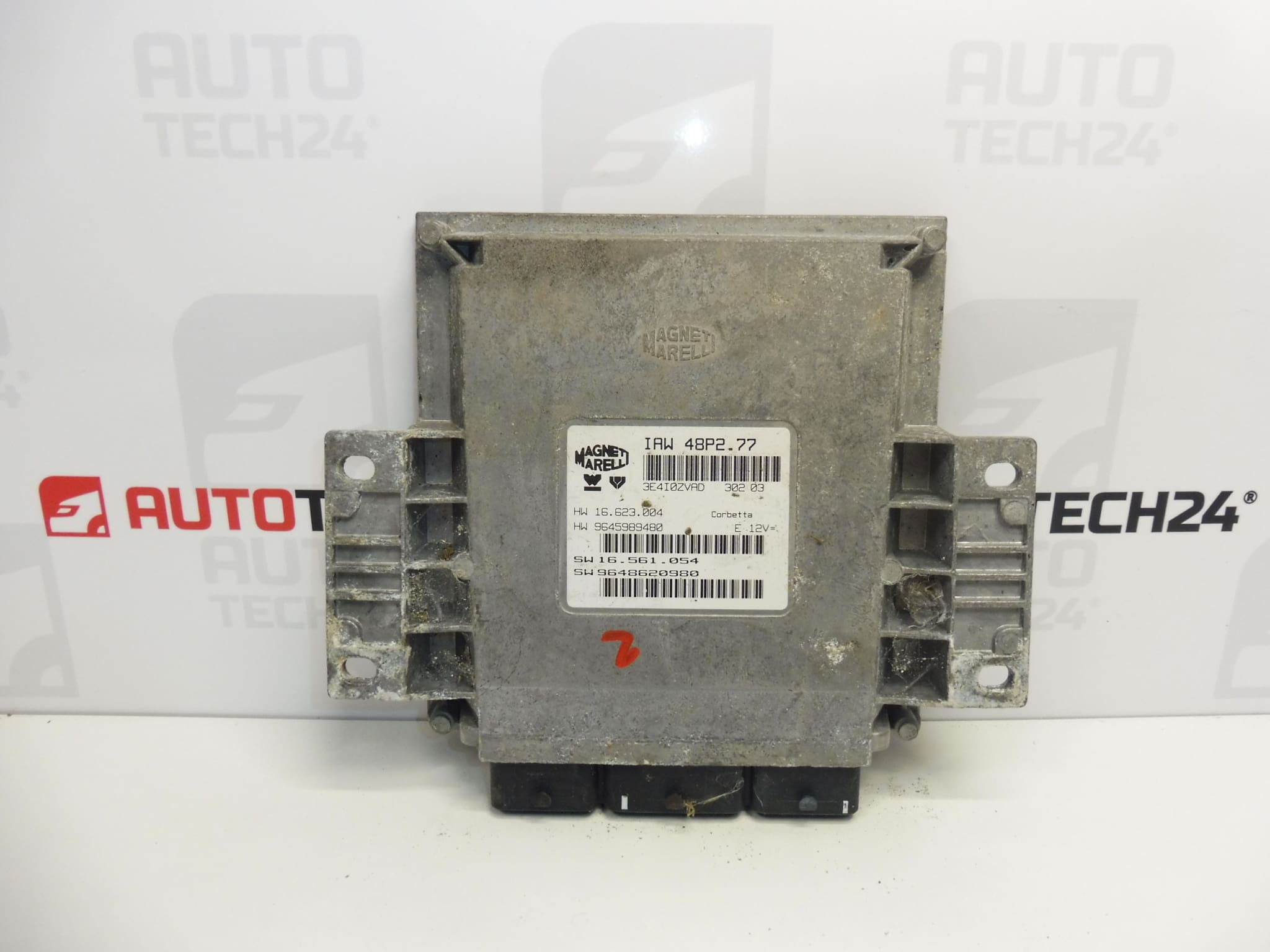
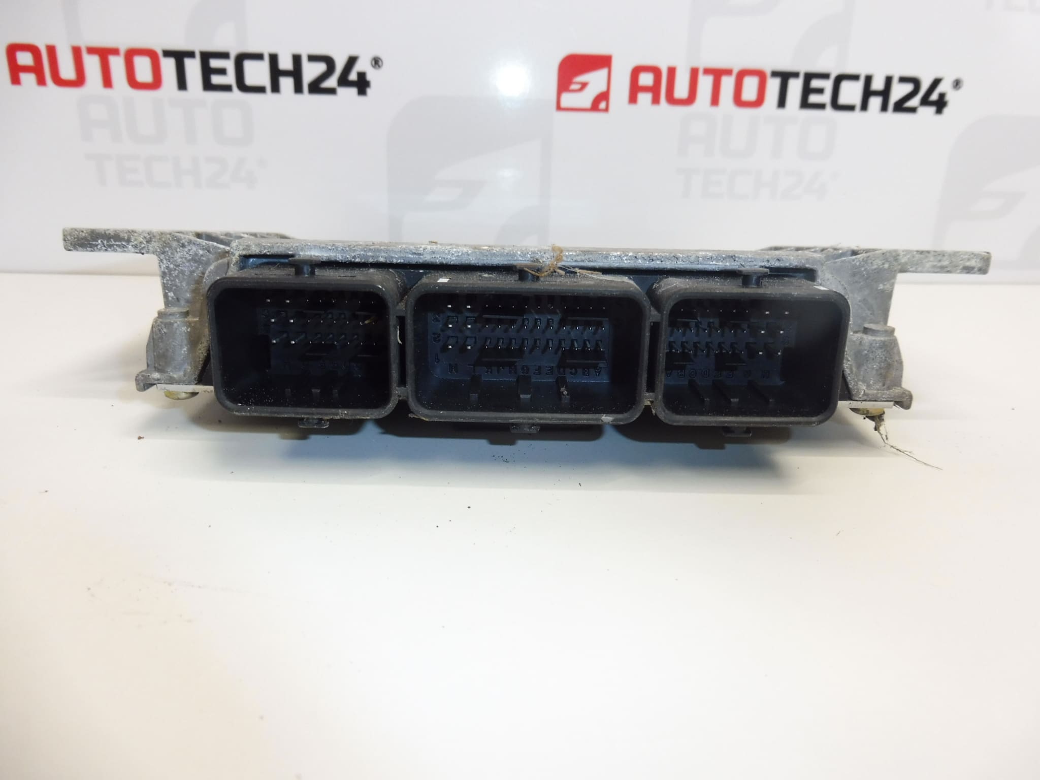
MAGNETI MARELLI IAW 48P2.77 control unit
From a PEUGEOT 206 1.1i
Part description
Used MAGNETI MARELLI IAW 48P2.77 injection control unit from a Peugeot 206 1.1i. This type of unit processes signals from sensors and controls the injection system, so it has a significant effect on starting and correct engine operation.
When looking for a replacement part, use the designation IAW 48P2.77 and the numbers 9648620980, 9645989480 and 1938NH as a guide. Matching the vehicle model alone is not enough: it is important to compare the identification of the original unit and ensure that data can be transferred or the unit adapted as required. This is an option for replacing a faulty unit with a used part; its commissioning must be planned before installation.
Technical information
- Manufacturer: MAGNETI MARELLI
- Model: Peugeot 206
- Unit type: IAW 48P2.77
- Part category: injection control unit
- Part taken from: PEUGEOT 206 1.1i
- Condition: used part
- Additional numbers: 9648620980, 9645989480, 1938NH
- Additional designation in the documentation: NFP
Product codes
- Product codes: 9648620980, 9645989480, 1938NH
- Type designation: IAW 48P2.77
- Model: Peugeot 206
Installation recommendations
In general, the following applies to this type of part: replacing an injection control unit usually involves more than simply reconnecting the connectors mechanically. The following procedure is general; the exact steps for removal, disconnecting the power supply and programming depend on the specific vehicle model and version.
1) Before installation
- Compare the IAW 48P2.77 designation, product numbers and connector configuration with the original unit. Any differences must be assessed using the service documentation.
- Inspect the used part’s housing, mounting points, connectors and contacts. Pay attention to signs of moisture, corrosion, cracks and bent pins.
- Verify the cause of the original fault. A power supply, grounding or wiring fault can mimic a faulty unit and may also damage the replacement.
- Decide in advance how the unit’s data will be transferred or how it will be adapted. Keep the original unit available for data reading, if its condition allows.
2) Tools and materials required
- Standard hand tools suitable for the unit’s mounting and access.
- Diagnostic equipment for PSA vehicles and, depending on the method chosen, equipment for reading and writing unit data.
- A multimeter for checking electrical circuits in accordance with the service documentation.
- Tools for labeling connectors, a suitable electrical contact cleaner and clean work supplies.
- A suitable regulated power supply, if required by the programming procedure.
3) Step-by-step installation procedure
- Run an initial diagnostic and record the available identification details, configuration and faults of the original unit.
- Check the power and ground circuits as well as the associated wiring. Rectify any faults found before connecting the replacement part.
- If possible, arrange for the original unit’s data to be professionally read and backed up using a procedure compatible with the equipment being used.
- Switch off the ignition, allow the electronic systems to enter their rest state, and disconnect the battery in accordance with the manufacturer’s procedure.
- Access the unit in accordance with the service documentation for the specific vehicle. Before disconnecting anything, note the wiring routing and connector connections.
- Release the connector locks and disconnect the connectors without pulling on the wires. Do not force the locking mechanisms.
- Undo the fasteners and remove the original unit. Check the condition of the brackets, connectors and any protective components.
- Arrange the chosen preparation of the replacement unit, such as data cloning or virginization. Follow the professional procedure and equipment being used when deciding the order of programming steps.
- Position the replacement unit, secure it in accordance with the documentation and connect the connectors. Check that they are fully seated and locked.
- Reconnect the battery following the manufacturer’s procedure. Depending on the method chosen, complete initialization, configuration and key adaptation.
- Run a diagnostic check of communication and verify that starting is enabled. Start the engine only after completing the required procedures.
- Check engine operation and, after the final inspection, refit any covers and other access components that were removed.
4) Post-installation checks and test drive / function verification
Check communication with the unit, starting, engine stability and any warning messages. Make sure the connectors are locked and the wiring is neither taut nor pinched. If the engine is running correctly and the vehicle is safe to drive, take it for a short test drive. Then run diagnostics again and assess any recurring faults.
5) Common installation mistakes and how to avoid them
- Choosing a part based only on the car model: also compare the unit type, product numbers and adaptation requirements.
- Connecting a used unit without preparation: arrange data cloning or appropriate initialization and coding in advance.
- Replacing the unit without fixing the original cause: first check the wiring, power supply, grounding and associated circuits.
- Damaging the connectors: always release the locks first and do not pull on the wiring harness.
- Interrupting the power supply while writing data: follow the programming equipment requirements and ensure a stable power supply.
Installation and coding – important
- The unit is used and is “paired” with the original vehicle (VIN/PIN/keys).
- Options for commissioning:
- Cloning data from the old unit (EEPROM/Flash) – after cloning, the unit is plug and play.
- Virginization followed by initialization/telecoding via DiagBox (possibly online) + key adaptation.
- We recommend having this done by a professional with PSA service equipment (DiagBox/Lexia/PP2000).
- Always disconnect the battery before removal/installation and follow the manufacturer’s procedure to avoid damaging the unit.
Reasons why the part may be damaged
The following factors can generally cause injection control units to become damaged. This is not a description of faults found on this specific unit.
- Moisture and corrosion: water ingress can damage the contacts and internal electronics.
- Electrical overvoltage or incorrect polarity: improper handling of the power supply can damage electronic circuits.
- Short circuits in the wiring or connected components: these can overload the unit’s output circuits.
- Thermal stress and vibration: over time, these contribute to the aging of components and electrical connections.
- Unqualified work: incorrectly opening the housing, handling the contacts or interrupting a data write can damage the unit or make it inoperative.