Description
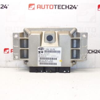
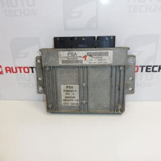
SAGEM control unit for Citroen Xsara Picasso 1.8 16V 6FZ
Part description
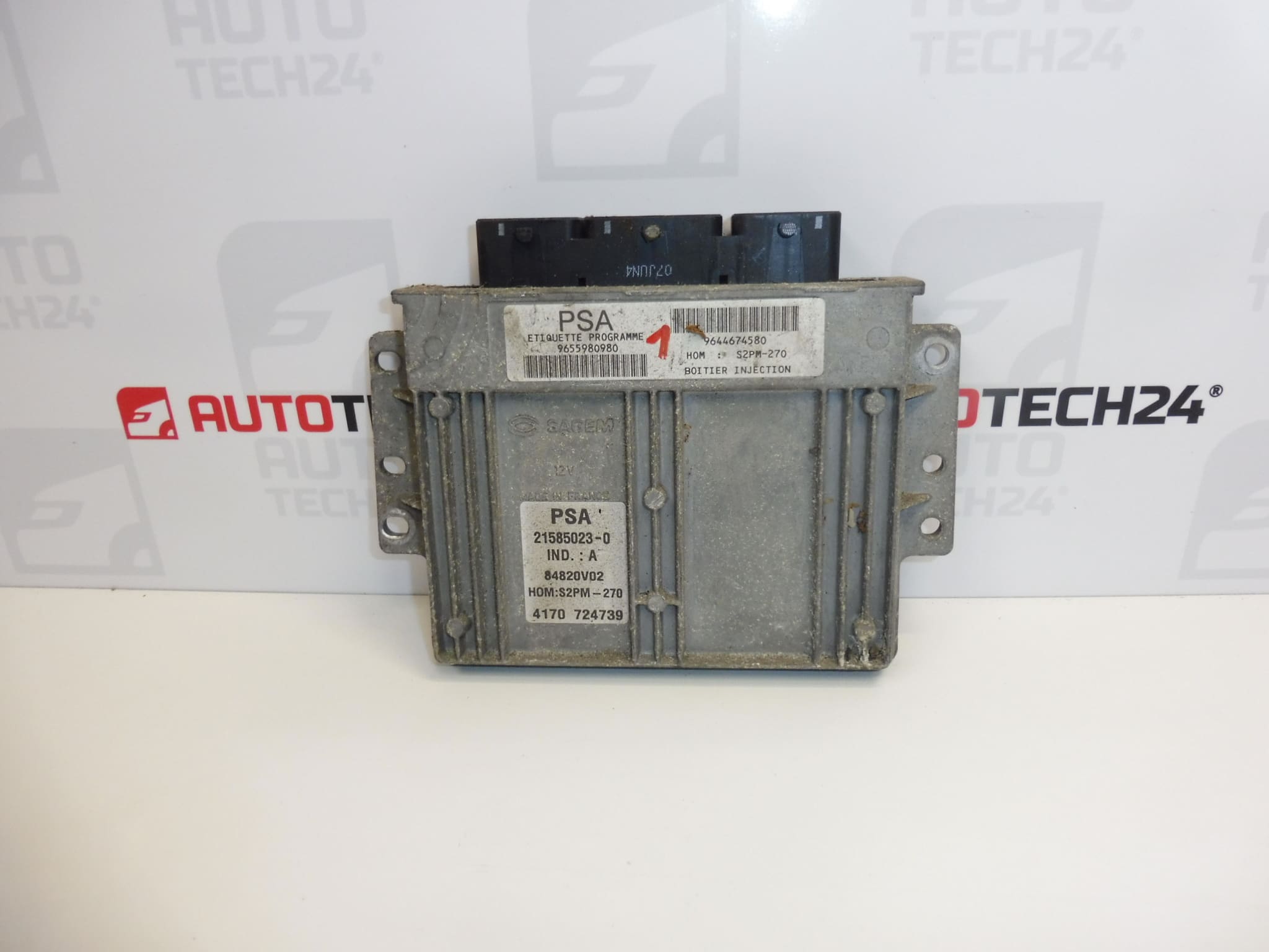
Used Sagem S2PM-270 injection control unit for Citroën Xsara Picasso 1.8 16V with engine code 6FZ. The control unit processes data from sensors and controls the injection system and other engine functions. Its proper operation is important for starting and smooth engine running.
When looking for a replacement part, use the S2PM-270 marking and product numbers 9655980980, 9644674580, 194216 and 194211 as your main references. Before replacement, it is important to confirm that the original unit is faulty and to allow for transferring data or adapting the used unit to the vehicle. Simply connecting the plugs is generally not enough to get it working.
Technical information
- Manufacturer: SAGEM
- Model: Citroën Xsara Picasso
- Unit type: S2PM-270
- Part type: engine injection control unit
- Engine: 1.8 16V
- Engine code: 6FZ
- Condition: used part
- Other numbers: 9655980980, 9644674580, 194216, 194211
- Other designation in documentation: NFP
Product codes
- Product codes: 9655980980, 9644674580, 194216, 194211
- Type designation: Sagem S2PM-270
- Model: Citroën Xsara Picasso
The numbers listed are used to identify the part. Compare them with the markings on the original unit; the same engine or a similar appearance alone does not guarantee that the hardware and software versions are interchangeable.
Installation recommendations
In general, the following applies to this type of part: replacing an injection control unit requires diagnostics and usually also work with stored data. The following procedure is general; the exact removal, electrical checks and method of commissioning depend on the specific vehicle and unit version.
1) Before installation
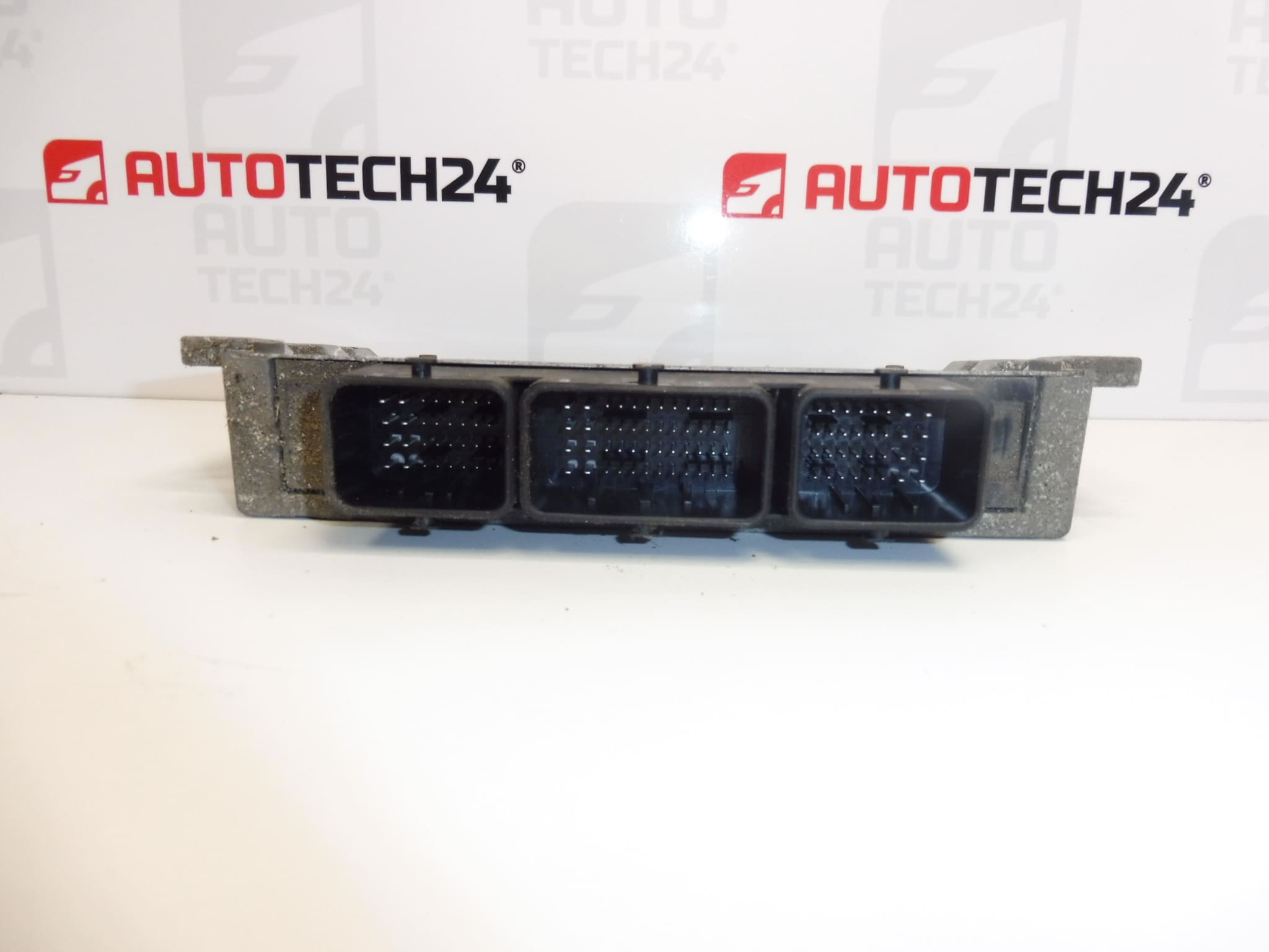
- Compare the manufacturer, type designation, product numbers, connector configuration and mounting with the old unit.
- Inspect the casing, connectors and contacts of the used part. Look for cracks, deformation, corrosion, moisture and signs of overheating.
- Use diagnostics and measurements to check the power supply, grounding and related wiring. A wiring, sensor or actuator fault can mimic a unit failure or damage the replacement unit.
- If the original unit can be read, back up its data and configuration before replacement.
2) Tools and materials required
- Standard hand tools suitable for the unit’s mounting and access to it.
- PSA diagnostic equipment and a suitable measuring instrument.
- Equipment for working with the unit’s data if cloning or virginization is required.
- Products suitable for gently cleaning electrical contacts and protection against electrostatic discharge.
- A suitable stabilized power supply for programming, according to the requirements of the equipment used and the service procedure.
3) Step-by-step installation procedure
- Perform initial diagnostics and save the detected faults and any available information about the original unit.
- Check the power supply, grounding and connected circuits. Resolve any external faults found before connecting the replacement part.
- Choose a suitable commissioning method and, if available, back up the original unit’s data.
- Switch off the ignition, allow the electronics to enter the sleep state according to the manufacturer’s procedure, and disconnect the battery.
- Access the unit according to the service procedure for the specific vehicle. Make a note of the wiring routing and connector layout.
- Release the connector locks and carefully disconnect the connectors. Do not pull on the wires or pry at the contacts.
- Release the mounting and remove the original unit. Check the bracket, surrounding area and for any signs of water ingress.
- Inspect the wiring harness connectors and address any causes of poor contact. Contacts must be clean and dry before connection.
- Have the replacement unit’s data prepared as required. Adapt the order of operations outside and inside the vehicle to the method chosen.
- Secure the unit, connect the connectors and check that their locks are engaged. The wiring must not be stretched or pinched.
- Reconnect the battery according to the manufacturer’s procedure and perform any required initialization, coding and key adaptation. Do not interrupt the power supply or communication during programming.
- Check diagnostic communication, start authorization and engine operation. Assess stored faults and complete the necessary functional checks.
4) Post-installation checks and test drive/function verification
- Check starting, stable engine operation and response to throttle input.
- Check warning lights, diagnostic data and whether any faults return after restarting the engine.
- If the engine runs properly and the vehicle is safe, take a short test drive and then perform a diagnostic check.
- If there are starting problems, first check pairing, the power supply and connections; do not automatically assume the replacement unit is faulty.
5) Most common installation mistakes + how to avoid them
- Replacing the unit without confirming the fault: first rule out problems with the power supply, grounding and related circuits.
- Choosing based on appearance alone: compare the markings and ensure the hardware and software versions are compatible.
- Skipping adaptation: plan for cloning or another suitable commissioning method before installation.
- Handling while powered: disconnect and connect the plugs only after safely disconnecting the battery according to the manufacturer’s procedure.
- Interrupting programming: ensure a stable power supply and a reliable diagnostic connection.
- Leaving the cause of the original damage unresolved: address water ingress, damaged wiring or a fault in a connected circuit before putting the unit into service.
Installation and coding – important
- The unit is used and is “paired” with the original vehicle (VIN/PIN/keys).
- Commissioning options:
- Cloning data from the old unit (EEPROM/Flash) – after cloning, the unit is plug and play.
- Virginization followed by initialization/telecoding via DiagBox (possibly online) + key adaptation.
- It is recommended that this be carried out by a professional with PSA service equipment (DiagBox/Lexia/PP2000).
- Always disconnect the battery before removal/installation and follow the manufacturer’s procedure to avoid damaging the unit.
Reasons why the part can become damaged
Injection control units can generally be damaged for the following reasons. This is not a description of the condition of this specific unit.
- Moisture and corrosion: water ingress or damaged connector protection can affect the contacts and internal electronics.
- Overvoltage and incorrect handling of the power supply: charging system faults, reverse polarity or an unsuitable jump-starting procedure can damage electronic circuits.
- Short circuits in wiring and connected components: these can overload the unit’s output circuits.
- Thermal stress and vibration: over time, these contribute to component aging and connection failures.
- Improper work: forcibly dismantling the unit, damaging the contacts or incorrect programming can cause it to stop working.