Description
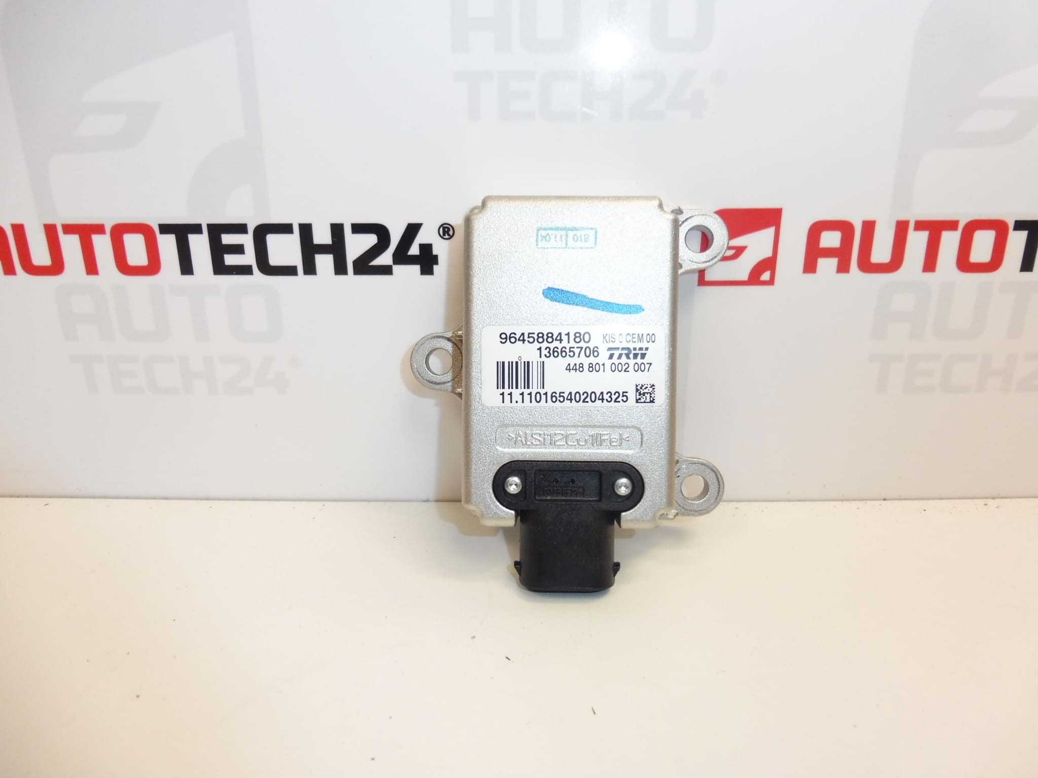
Kinetic ESP sensor TRW for Peugeot 407 vehicles
Double ESP sensor
Part description
The used TRW double ESP sensor for Peugeot 407 is part of the vehicle’s electronic stability control system. This type of sensor provides the ESP system with data about the vehicle’s movement, which is used to evaluate driving stability. The sensor must therefore function correctly for the stability control system to operate properly.
If you are looking for a replacement for a faulty sensor, base your selection primarily on the markings on the original part and its design. The item offered is listed in the source materials under numbers 9645884180, 13665706 and 454930. This used part offers a repair option without having to purchase a new sensor, provided it meets the requirements of the specific vehicle.
Technical information
- Manufacturer: TRW
- Model: Peugeot 407
- Part type: double ESP sensor
- System: ESP – electronic stability control system
- Condition: used part
- Additional number: 13665706
- Additional designation in the source materials: NFP
Product codes
- Product codes: 9645884180, 13665706, 454930
- Model: Peugeot 407
Compare the numbers with the markings on the removed sensor. Matching the vehicle model alone may not be enough to select the correct version.
Installation recommendations
The following procedure is a general guide to replacing an ESP sensor. The exact access to the part, how it is secured, and any adjustments required after replacement depend on the specific vehicle version and the manufacturer’s service instructions. This is a component of a safety system; if you are unsure, have the replacement carried out by a professional repair shop.
1) Before installation
- Use diagnostic equipment to check the cause of the fault. An ESP fault message may not be caused by the sensor itself; the cause could also be the connector, wiring, or power supply.
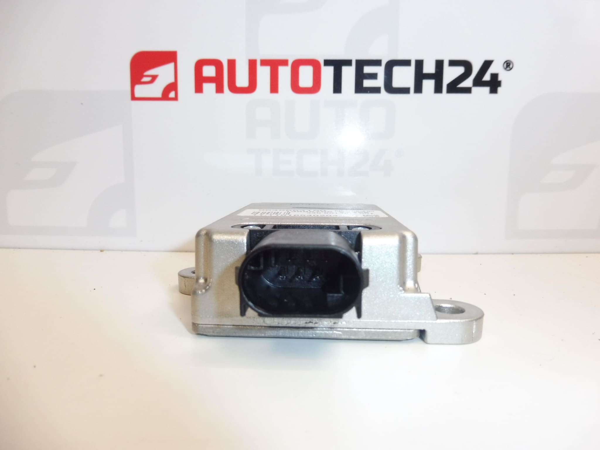
- Compare the part numbers, housing shape, connector, mounting points, and any alignment marks with the original part.
- Inspect the used sensor. Check for cracks, damaged mounts, contact damage, and signs of moisture or corrosion. Do not install a visibly damaged part.
- Check in advance whether the service procedure for the specific version requires calibration or basic settings after replacement.
2) Tools and materials required
- Standard hand tools suitable for the fasteners used.
- Tools for carefully releasing covers and connector locks, as needed.
- A clean, lint-free cloth and, if necessary, a product suitable for electrical contacts.
- Diagnostic equipment capable of communicating with the vehicle’s ABS/ESP system.
- Manufacturer service instructions for the specific vehicle version.
3) Step-by-step installation procedure
- Park the vehicle safely and secure it against movement.
- Before disconnecting the electrical system, read and record any ABS/ESP system fault codes.
- Switch off the ignition and allow the electronics to enter sleep mode as specified by the manufacturer. Disconnect the battery according to the service instructions.
- Access the sensor using the method specified for the specific vehicle version. Remove covers and nearby components without forcing them.
- Record the position and orientation of the original sensor, for example by taking a photograph. Correct orientation is essential for this type of part.
- Release the connector lock and disconnect the connector by pulling on its housing, not on the wires.
- Release the fastener and carefully remove the original sensor. Protect sensors from drops and impacts.
- Inspect the mounting surface, mounting points, and wiring. Have any moisture, corrosion, or damage professionally addressed first.
- Install the replacement sensor in the correct orientation and secure it according to the manufacturer’s instructions. The part must sit flush without tension and must not be loose.
- Reconnect the connector and check that its lock is engaged. Route the wiring so that it is not stretched, pinched, or exposed to chafing.
- Reinstall the removed components and restore the electrical power supply according to the manufacturer’s procedure.
- Perform a diagnostic check and any basic settings or calibration required for the specific version. After correcting the cause, clear the stored fault codes and check whether they return.
4) Checks after installation and function verification
- Check that the sensor is securely mounted, the connector is properly connected, and the wiring is undamaged.
- Check the ABS/ESP warning lights and use diagnostic equipment to verify the system status; the warning light going out on its own is not a complete check of the repair.
- If the system reports no active fault and the vehicle is safe to drive, take a short, gentle test drive in accordance with the service instructions. Do not deliberately induce a skid or trigger ESP intervention in normal traffic.
- Read the fault memory again after the drive. If the fault returns, continue diagnostics before using the vehicle normally.
5) Common installation mistakes and how to avoid them
- Replacing the part without confirming the cause of the fault: check the connector, wiring, and power supply as well.
- Incorrect sensor version: compare both the markings and the physical design with the original part.
- Incorrect orientation or loose mounting: follow the correct installation position and specified fastening method.
- Connector damage: always release the lock first, and do not pull on the wires.
- Skipping required settings: check the service procedure requirements in advance and use suitable diagnostic equipment.
Reasons why the part may be damaged
The following factors can generally cause damage or incorrect operation in ESP sensors. They do not describe the condition of the item offered.
- Moisture and corrosion, which can damage electrical contacts or electronics.
- Mechanical impact, dropping, or deformation of the mounting points, for example during careless handling or an accident.
- Electrical overload or improper work on the electrical system, which can damage sensitive components.
- Aging electronics and prolonged exposure to thermal stress.
- Loose mounting or an incorrect installation position, which can cause incorrect readings even without internal damage to the part.
A broken wire or poor contact in the connector can cause similar symptoms. Correct diagnosis before replacement helps avoid unnecessary work and recurring faults.