Description
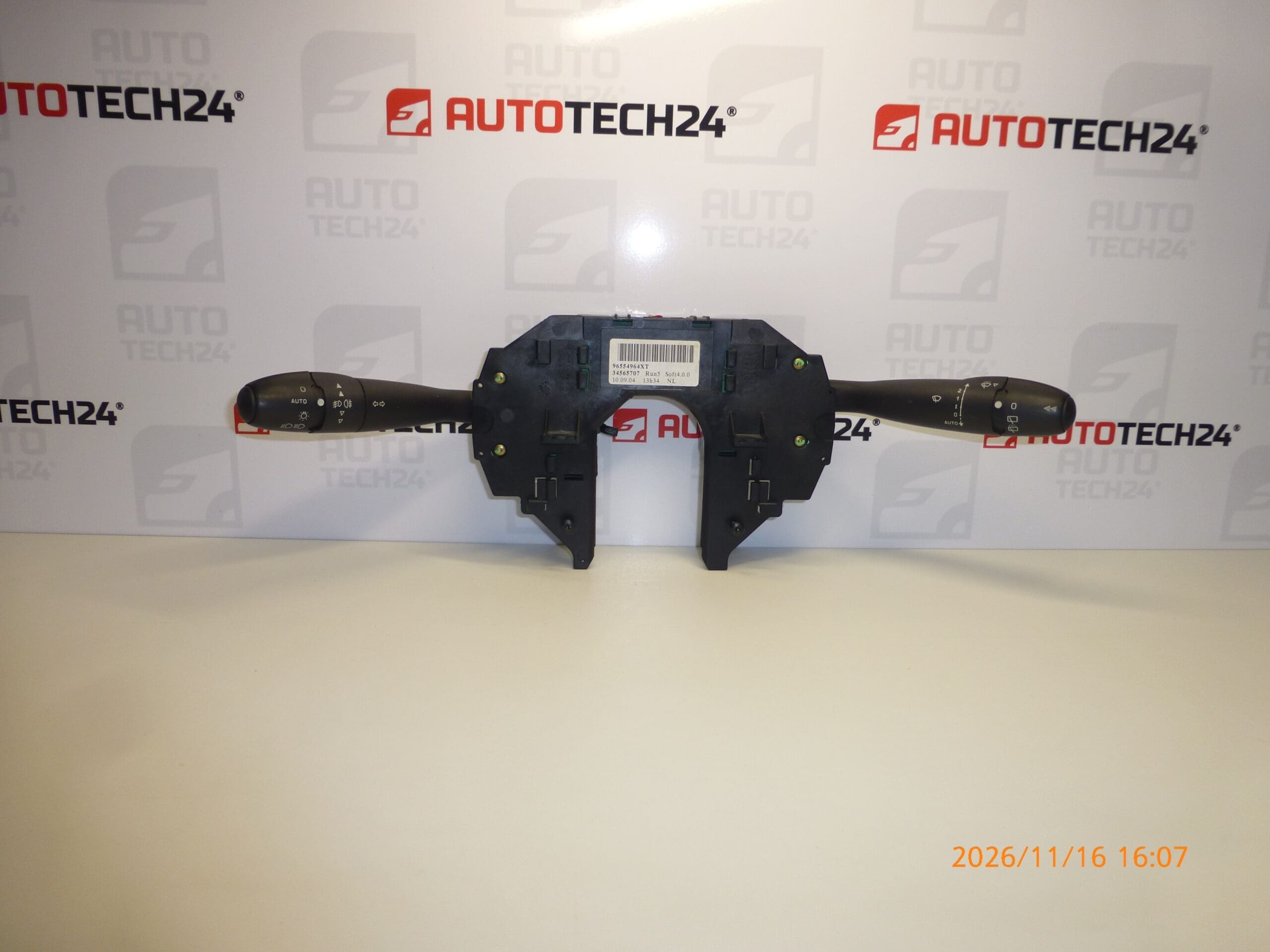
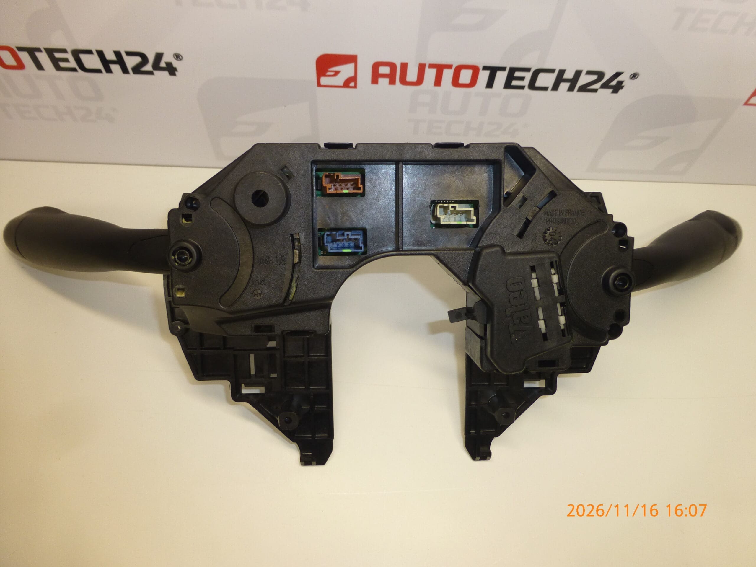
Steering column switches (stalks) VALEO CITROEN C4 PICASSO and GRAND PICASSO
Control the fog lights, front and rear wipers, wiper sensor and onboard computer
Part description
Used VALEO steering column switches for Citroën vehicles control the fog lights, front and rear wipers, wiper sensor function and onboard computer. They are a suitable choice when replacing damaged stalks or switches that do not respond reliably when operated.
When selecting a part, pay particular attention to the codes 96554964XT, 6242HL and 624348 and make sure it matches the original part in design. The model name alone is not enough: the connectors, mounting points and functions of the individual stalks are also important. Choosing the correct part will preserve convenient control of these functions directly from the steering column.
Technical information
- Manufacturer: VALEO
- Model: Citroën C4; Citroën C4 PICASSO. The long description also lists CITROEN C4 GRAND PICASSO.
- Other numbers: 624348; the designation NFP is also listed in the source materials.
- Part type: steering column switches – stalks
- Controlled functions: fog lights, front and rear wipers, wiper sensor, onboard computer
- Condition: used car part
- Model years and engine variants: not specified
Product codes
- Product codes: 96554964XT, 6242HL, 624348
- Additional designation: NFP
Before ordering, compare the designation on the original switch with the codes listed above. Also check that the functions, symbols on the stalks and electrical connectors match.
Installation recommendations
In general, the following applies to this type of part: the exact removal and installation procedure depends on the specific model and vehicle configuration. The following is a general procedure for replacing steering column switches, not a model-specific service guide. If replacement requires work on the steering wheel or airbag system, have this work carried out by a qualified mechanic.
1) Before installation
- Compare the product designation, assembly shape, mounting points, connectors and stalk functions with the old part.
- Inspect the housing, clips and contacts. Look for cracks, deformation, corrosion and signs of overheating or moisture.
- Gently check the movement of the stalks and switches. Do not force the mechanism.
- Check the cause of the fault: similar symptoms can also be caused by wiring, a connector or a related electrical circuit.
2) Tools and materials required
- Standard hand tools with suitable bits for the fasteners used.
- Plastic tools for carefully removing covers.
- A flashlight, a clean cloth and supplies for labeling the wiring or keeping screws organized.
- The service procedure for the specific vehicle; suitable automotive diagnostic equipment if required.
3) Step-by-step installation procedure
- Park the vehicle in a safe place, secure it against movement, and switch off the ignition and all electrical accessories.
- Follow the manufacturer’s service procedure to allow the electronics to enter sleep mode, disconnect the battery and observe the prescribed waiting time for safe working.
- Carefully remove the covers needed to access the switches. Do not pry them off by force; first locate all screws and clips.
- If access requires removing the steering wheel or airbag, proceed only in accordance with the relevant service procedure and if you have the required expertise. Do not test airbag connectors with a standard test light or multimeter.
- Record the wiring route and connector positions, for example by taking a photo, so everything can be returned to its original arrangement.
- Release the connector locks and disconnect them by gripping their housings. Do not pull on the wires.
- Release the original assembly’s fasteners and carefully remove it. If a rotary contact unit is exposed during the work, do not alter its position without authorization.
- Compare the removed part with the replacement once more. Check the mating surfaces, mounting points and condition of the surrounding wiring.
- Fit the replacement switches without force and secure them according to the manufacturer’s procedure. Do not deform plastic parts by overtightening.
- Connect the connectors until they are properly secured and route the wiring so that it is not pinched, stretched or in contact with moving parts.
- Reinstall the removed components and covers. Reconnect the battery according to the manufacturer’s procedure and carry out the prescribed procedure to restore the electronics to operation.
4) Checks after installation and function testing
- With the vehicle stationary, first check all the functions listed: fog lights, front and rear wipers, wiper sensor controls and the onboard computer, as equipped.
- Test the wipers on a wet windshield. Check the sensor function under the appropriate conditions, as described in the vehicle owner’s manual.
- Check that the stalks move freely, the covers are fitted correctly and there are no unusual messages or warning lights.
- Only take a short test drive after the stationary checks have been completed successfully. Have any remaining faults diagnosed rather than repeatedly replacing parts without identifying the cause.
5) Common installation mistakes and how to avoid them
- Selecting a part based only on the car model: also compare the codes, connectors and range of functions of the original stalks.
- Disconnecting connectors by pulling on the wires: release the clip first and grip the connector housing.
- Wiring pinched under a cover: check its routing and make sure there is sufficient clearance before refitting the covers.
- Forcing the part into place or overtightening the fasteners: if there is resistance, check the position of the part and clips; do not use more force.
- Failing to disconnect the power safely: always follow the manufacturer’s procedure, especially when working near the airbag system.
Reasons why the part may become damaged
The following are general causes of damage that may occur with steering column switches. They are not a description of defects found on this specific item.
- Mechanical wear: frequent use gradually places strain on the switching mechanisms, detents and contacts.
- Excessive force during operation: rough handling or an impact to a stalk can damage the plastic parts and internal mechanism.
- Moisture and dirt: these may impair switch movement or cause corrosion of the electrical contacts.
- Damaged electrical connections: a loose or corroded contact can cause intermittent operation and localized overheating.
- Careless removal: prying, pulling on the wires and incorrect fitting can damage the connectors, clips and assembly housing.