Description
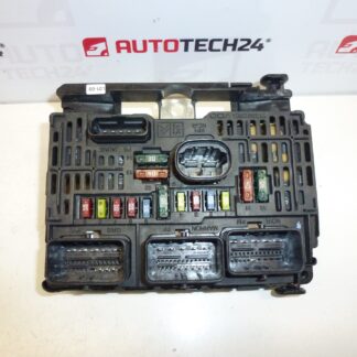
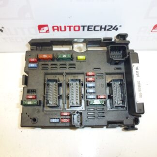
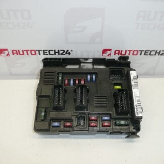
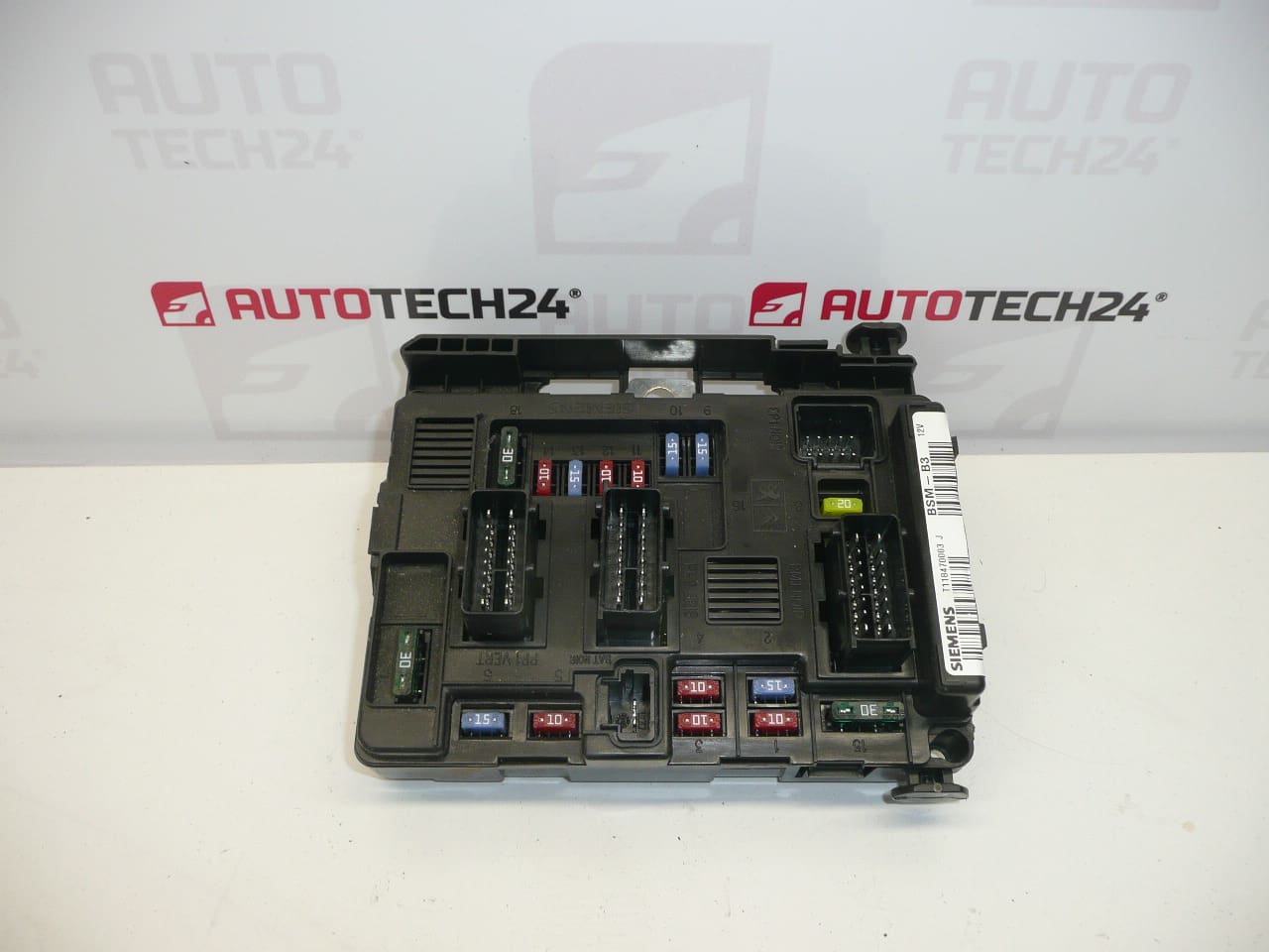
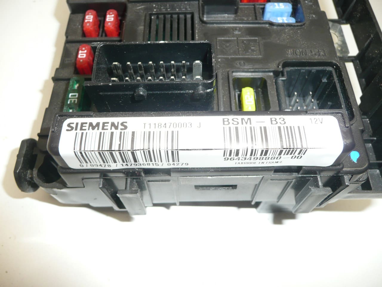
BSM B3 SIEMENS CITROEN PEUGEOT 9643498880
This is a used part with a guarantee of functionality
Damage to one of the holders is possible – it does not affect functionality
Part description
BSM (engine unit / fuse and relay module in engine compartment) type BSM B3 Siemens for Citroën and Peugeot cars. Searched often by the number 9643498880. The part is intended as a replacement for a non-functional unit that can cause various electrical faults in the power supply and circuit switching.
This is a used part with a guarantee of functionality. For this piece, it is stated that there may be damage to some holder, which does not affect functionality (typically mechanical damage to the plastic during disassembly/handling).
Technical information
- Manufacturer: Siemens
- Model: not specified
- Other numbers: 9643498880-00, T118470003, G, J, 6500Y3
Product codes
- Product codes: 9643498880, 9643498880-00, T118470003, 6500Y3
Marks/models mentioned: Citroën Berlingo, Citroën C2, Citroën C3, Citroën C3 Pluriel, Citroën C5, Peugeot Partner.
Installation recommendations
Generally/typically for BSM units, the exact procedure may vary depending on the specific model and make of the car. Below is a practical general procedure for BSM replacement.
1) Before assembly (checks of the used part, what to compare with the old part)
- Check the match of the product codes (minimum 9643498880, possibly 6500Y3 and additional numbers on the label).
- Compare the design of the connectors (number, shape, mechanical keying) with the old piece.
- Visually check the condition of the pins in the connectors (bent/pressed pins, oxidation, dirt).
- Take note of the damage to the holders – check that the unit can be securely held and that the connectors are properly secured.
2) Necessary tools and materials (in general, without specific extra parts)
- Basic set of ratchets/bits and screwdrivers
- Plastic pry bar for releasing covers/connectors (according to design)
- Cleaning agent for electrical contacts (as needed)
- Protective gloves, possibly a flashlight
3) Step-by-step assembly procedure
- Turn off the ignition, remove the key and let the car “sleep” for a short time (typically a few minutes).
- Disconnect the battery (minus pole) and ensure that the terminal cannot accidentally touch the pole.
- Get access to the BSM unit (folding/unlocking the covers depending on the vehicle version).
- Before disconnecting, label the connectors or take a photo for correct connection.
- Step by step unlock and disconnect the connectors (don’t grab the cables, but the connector body/fuse).
- Unclamp the unit and remove it from the holder.
- Compare the old and new unit “side by side” (connectors, latches, orientation, number plate).
- Insert the unit into the holder and seat it properly (without straining it to sit straight).
- Plug the connectors back in the correct order and check the seat and fuses.
- Reinstall all covers and secure the cable routing so that it does not chafe or strain.
- Connect the battery (minus pole) and perform a basic initialization of the car according to common practice (if needed).
- Turn on the ignition and verify that there are no power outages and that the car responds normally.
-
4) Post-assembly checks and test drive/function verification
- Check that all connectors are tight and there is no “loose” wire anywhere.
- Verify basic electrical functions that were initially problematic (typically power/switched circuits).
- After a short test drive, visually check the fitment again and make sure nothing gets hot or smells like electricity.
5) The most common assembly mistakes + how to avoid them
- Disconnecting/connecting without disconnected battery → risk of damage to electronics; always disconnect the minus pole first.
- Not clicked connectors → random outages; always check the fuses and correct seating after connection.
- Swapping connectors → avoid markings/photos before disassembly.
- Pull the cables when disconnecting → release the connectors by their body and fuses.
- Ignoring oxidation/dirt in the connectors → if necessary, clean the contacts and let them air out.
Reasons why the part is damaged
- Moisture and oxidation in the connectors or in the unit space (deteriorated contact, transition resistances).
- Temperature stress and aging of materials (plastic, solder joints, relays).
- Overloading electrical circuits (e.g. short circuit in wiring or appliance) leading to damage to internal parts.
- Incompetent handling during disassembly/assembly (broken holders, damaged connector locks).
- Voltage fluctuations when disconnecting/connecting the battery incorrectly or during charging failure.