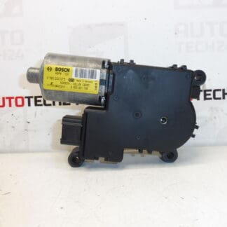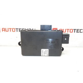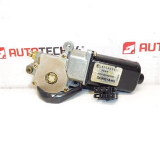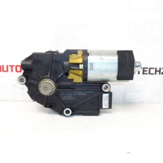
Description
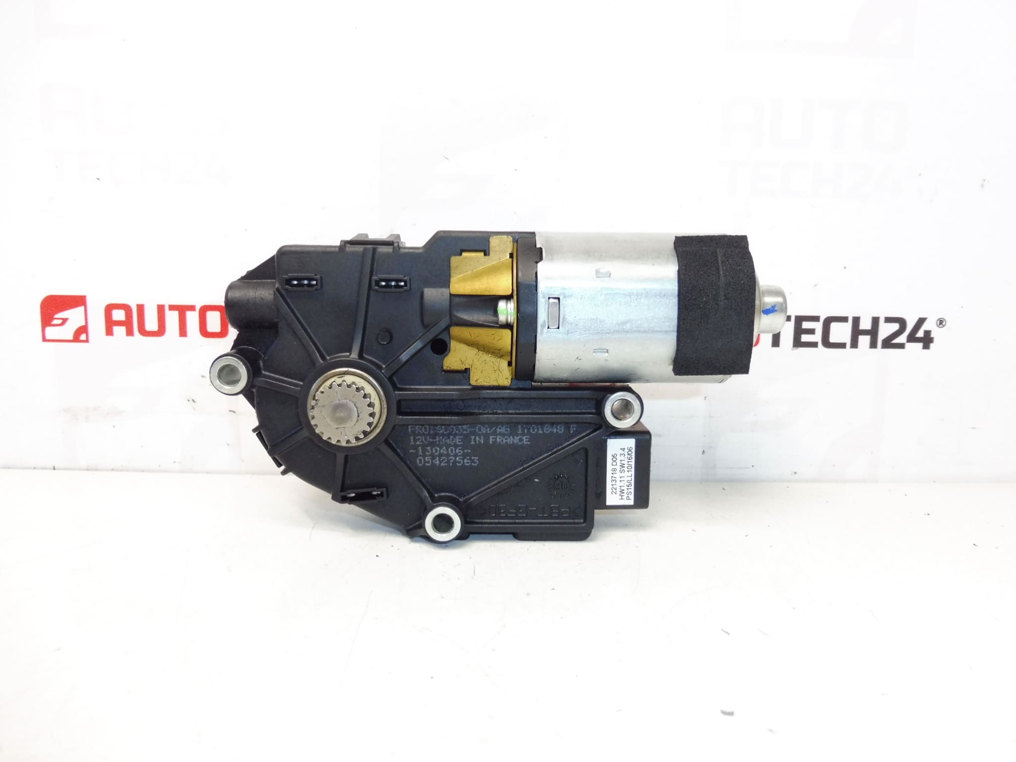
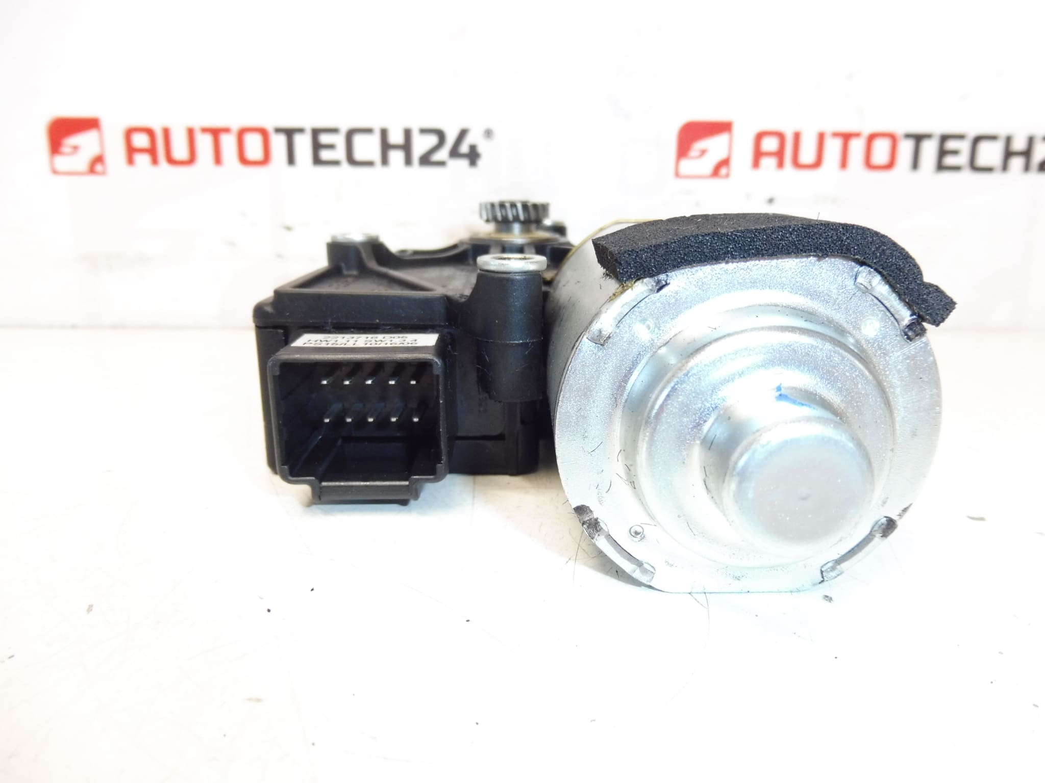
Electric motor for sunroof (sliding roof) for Citroën and Peugeot vehicles
The electric sunroof motor is a direct replacement part designed for Citroën C5 X7 and Peugeot 407 vehicles. It operates the sliding/tilt mechanism of the roof glass, converting electrical input into rotational movement that drives the sunroof gearbox and rack. This component is suitable for professional workshops and experienced DIY mechanics who perform sunroof repairs and maintenance.
Function and Fitment
This motor drives the sunroof gearset to open, close and tilt the roof glass smoothly. It is fitted behind the headliner, mounted to the sunroof gearbox assembly and connected to the vehicle wiring harness via a plug. Typical fitment applications include Citroën C5 X7 and Peugeot 407 models; fitment is commonly referenced by part numbers 96589697BJ and 8401EW.
How It Is Replaced
- Disconnect the negative battery terminal before any work to avoid short circuits and accidental motor activation.
- Remove the interior trim and headliner access panels to reach the sunroof mechanism—this usually requires removing trim clips and fasteners around the roof opening.
- If necessary, remove the sunroof glass or move it to a service position following the vehicle procedure to gain access to the motor housing.
- Unplug the electrical connector and unscrew the motor from the gearbox. Note the position of the motor and gear engagement to ensure correct reinstallation.
- Install the new motor, secure fasteners to the manufacturer-recommended torque if available, reconnect the electrical plug, realign the sunroof and test operation before refitting trim.
Installation Recommendations
- Always disconnect the battery before starting work.
- Keep track of all fasteners and trim clips; use protective covers to avoid scratching the headliner or glass.
- Inspect the sunroof tracks and guides for debris, corrosion or damage and clean/lubricate with suitable grease before final assembly.
- After installation, cycle the sunroof several times to verify smooth operation and check for abnormal noises, binding or leaks.
- If any electronic initialization is required by the vehicle’s comfort module, follow the manufacturer procedure or consult a workshop with PSA diagnostic equipment.
Common Failure Causes
Sunroof motors typically fail due to mechanical wear, water ingress, or overload conditions. The most frequent causes are worn brushes or armature wear, stripped or damaged worm gears, contamination and corrosion from moisture, and excessive resistance caused by misaligned or dirty tracks that overload the motor. Intermittent operation or unusual noises are early warning signs that the motor or gearbox needs attention.
Expected Service Life
Service life varies with usage, environmental exposure and maintenance. Motors on vehicles in harsh climates or with clogged drain channels and unlubricated tracks will fail sooner. Regular inspection and track lubrication can significantly extend life.
Technical Information
- Manufacturer: Stellantis (Citroën / Peugeot)
- Model: Citroën C5 X7; Peugeot 407
- Product Codes: 96589697BJ, 8401EW
- Other Numbers: No additional cross-reference numbers provided
Why Choose This Part
This sunroof motor is specified for common Citroën and Peugeot platforms and is identified by widely used part numbers for easy sourcing. It is intended for installers who require a direct-fit motor to restore proper sunroof function and to eliminate noise, stalling or non-operation caused by a failed unit.