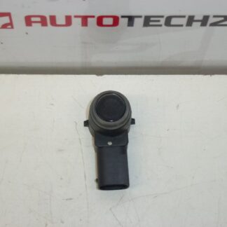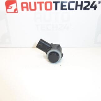
Description
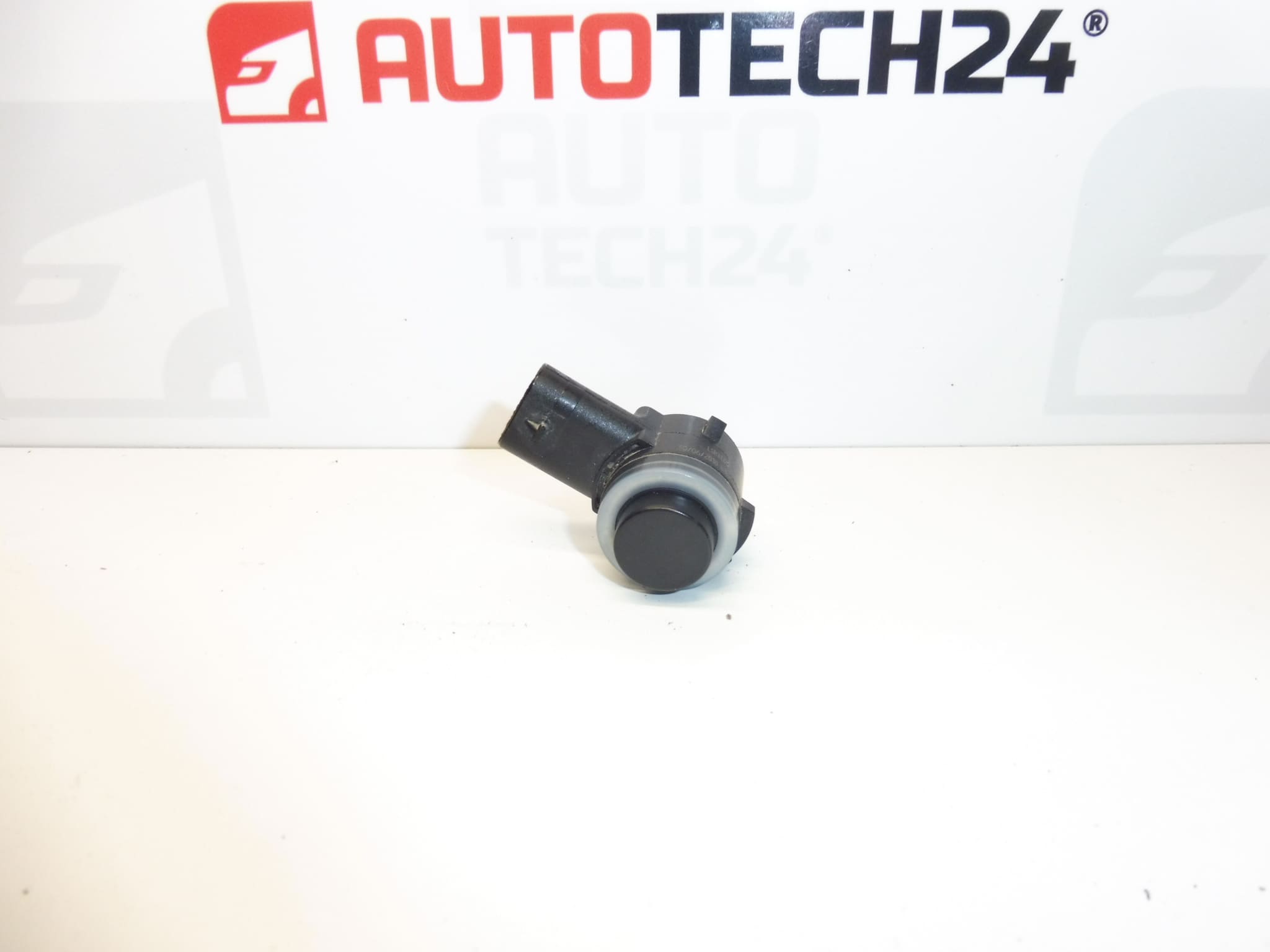
Parking sensor for CITROËN and PEUGEOT vehicles and other models in the group
The rubber seal may not be included
Part description
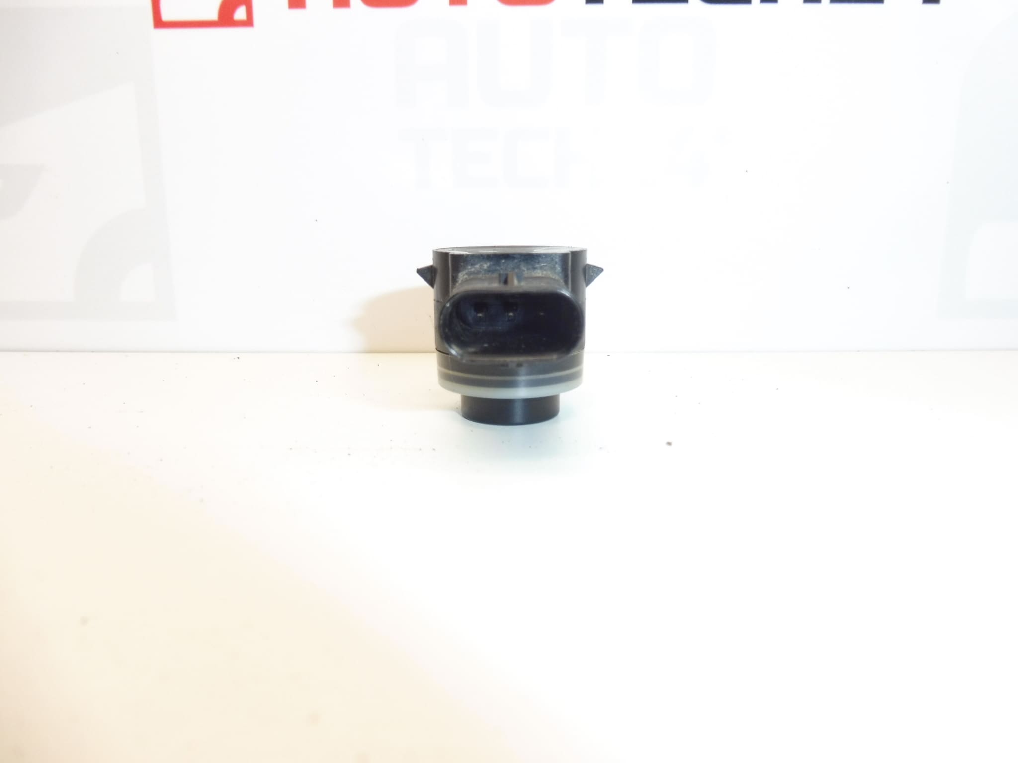
Used Citroën Peugeot PDC parking sensor with part numbers 9813348377 and 1633559380, designed for the parking assist system. This type of sensor helps detect obstacles while parking and sends information to the system, which alerts the driver. Replacing a faulty sensor may restore the proper operation of the parking assist system if the sensor itself is the cause of the fault.
According to the supplied information, this part is listed for the Citroën Berlingo K9, FIAT DOBLO III, OPEL COMBO E K9, PEUGEOT RIFTER and Toyota ProAce City. When selecting a part, primarily compare the product number, connector and mounting design with the original sensor; the model name alone is not sufficient guidance. This used part offers a cost-effective repair option without replacing the entire parking system.
Technical information
- Manufacturer: not specified; the supplied information lists the designation Stellantis CITROEN PEUGEOT.
- Model: Citroën Berlingo K9; FIAT DOBLO III; OPEL COMBO E K9; PEUGEOT RIFTER; Toyota ProAce City.
- Other numbers: not specified.
- Part type: PDC parking sensor, an electrical component of the parking assist system.
- Condition: used part.
- Seal: the rubber seal may not be included.
- Specific mounting position: not specified.
Product codes
- Product codes: 9813348377, 1633559380.
Both numbers can be used to look up the part. Before replacing it, compare the original sensor’s markings and design with the replacement sensor.
Installation recommendations
The following procedure is general guidance for PDC parking sensors. Access to the sensor, how the bracket is released and any system setup required depend on the specific model and vehicle configuration. Follow the vehicle manufacturer’s service procedure.
1) Before installation
- Verify that the fault is actually caused by the sensor and not by damaged wiring, a connector or another part of the parking system. Use suitable diagnostic equipment if necessary.
- Compare the product numbers, body shape, connector, connector keying and locking features with the original part.
- Inspect the used part: it must not have an obviously cracked body, damaged contacts or a deformed mounting.
- Check that the rubber seal is present and in good condition. It may not be included. Reuse the original seal only if it is suitable, flexible and undamaged.
2) Tools and materials required
- Standard hand tools suitable for the fasteners on the specific vehicle.
- Plastic trim removal tools for gently releasing covers and clips.
- A soft cloth and a cleaner suitable for the relevant surfaces; electrical contact cleaner if required.
- Suitable vehicle diagnostic equipment for identifying the fault and subsequently checking operation.
- A suitable, undamaged seal if required for the specific configuration.
3) Step-by-step installation procedure
- Park the vehicle safely, secure it against movement and switch off the ignition.
- Prepare the vehicle’s electrical system for the work in accordance with the service procedure; disconnect the battery if required, following the specified procedure.
- Access the sensor using the procedure for the specific vehicle. If surrounding parts need to be removed, protect their surfaces and clips from damage.
- Before removal, note the sensor’s orientation, how it is seated and the routing of the wiring.
- Release the connector lock and carefully disconnect the connector. Do not pull on the wires.
- Release the bracket’s locking features and remove the original sensor without forcing it out.
- Inspect the bracket, contact surfaces, seal and wiring. Remove any dirt and address any damage before installing the replacement part.
- Compare the two sensors side by side. Prepare a suitable rubber seal if the specific configuration uses one.
- Fit the replacement sensor in the correct orientation and secure it in the bracket. The seal must not be pinched, and the sensor must not be left loose.
- Connect the connector until it is properly locked and route the wiring so that it is not stretched, pinched or exposed to abrasion.
- Reinstall the removed parts, restore the power supply in accordance with the manufacturer’s procedure and check that the system works.
4) Post-installation checks and function verification
- Check that the sensor is seated firmly, the seal is positioned correctly and the connector is locked.
- Activate the parking system as specified for the vehicle and check for any fault messages or persistent false alerts.
- Test the function in a safe area using a clearly visible inanimate obstacle. Do not rely solely on the parking assist system and do not use a person as a test obstacle.
- If the fault persists, check the diagnostics, wiring and other system components. Replacing the sensor alone may not resolve a fault caused elsewhere.
5) Common installation mistakes and how to avoid them
- Choosing based only on appearance: also compare the part number, connector and mounting.
- Missing or damaged seal: before fitting, check whether the specific configuration requires one and ensure that it is seated correctly.
- Forcing the sensor into the bracket: first check its orientation and the condition of the clips.
- Connector not fully engaged or wires pinched: perform a visual check before closing up the access area and gently verify that the connector is locked.
- Covering the active surface with paint or dirt: keep the surface clean and apply any surface coating only in accordance with the manufacturer’s instructions.
Reasons why the part gets damaged
Common causes of damage or malfunction in parking sensors generally include:
- Mechanical impact while parking or a stone strike that damages the sensor body or active surface.
- Moisture and contact corrosion caused by a damaged seal or connector.
- Damaged bracket or incorrect seating, preventing the sensor from remaining in the correct position.
- Strained wiring, broken wires or a loose connection, which can mimic a fault in the sensor itself.
- Dirt, ice or an unsuitable layer of paint on the active surface, which can reduce detection even without permanently damaging the sensor.
- Rough removal or cleaning, particularly prying on the sensor body or using a high-pressure jet from very close range.