Description
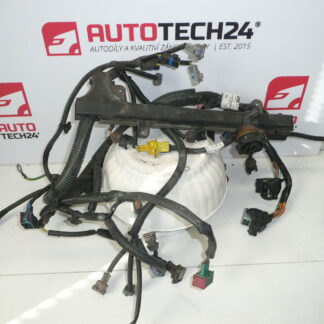
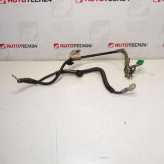
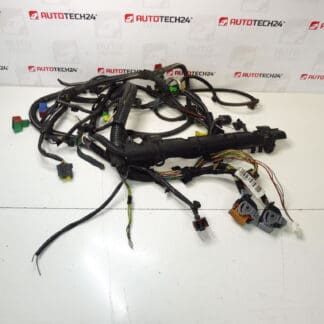
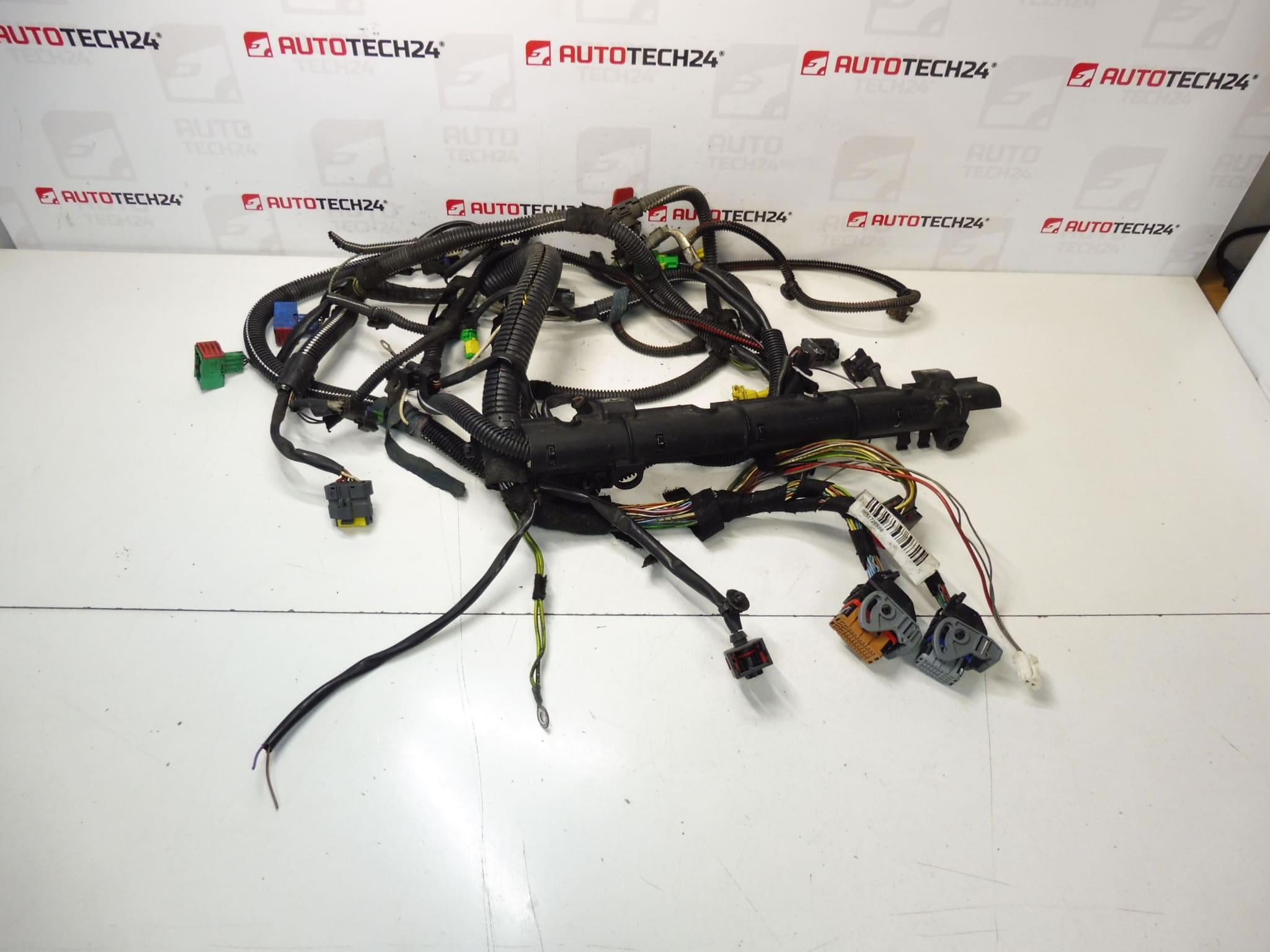
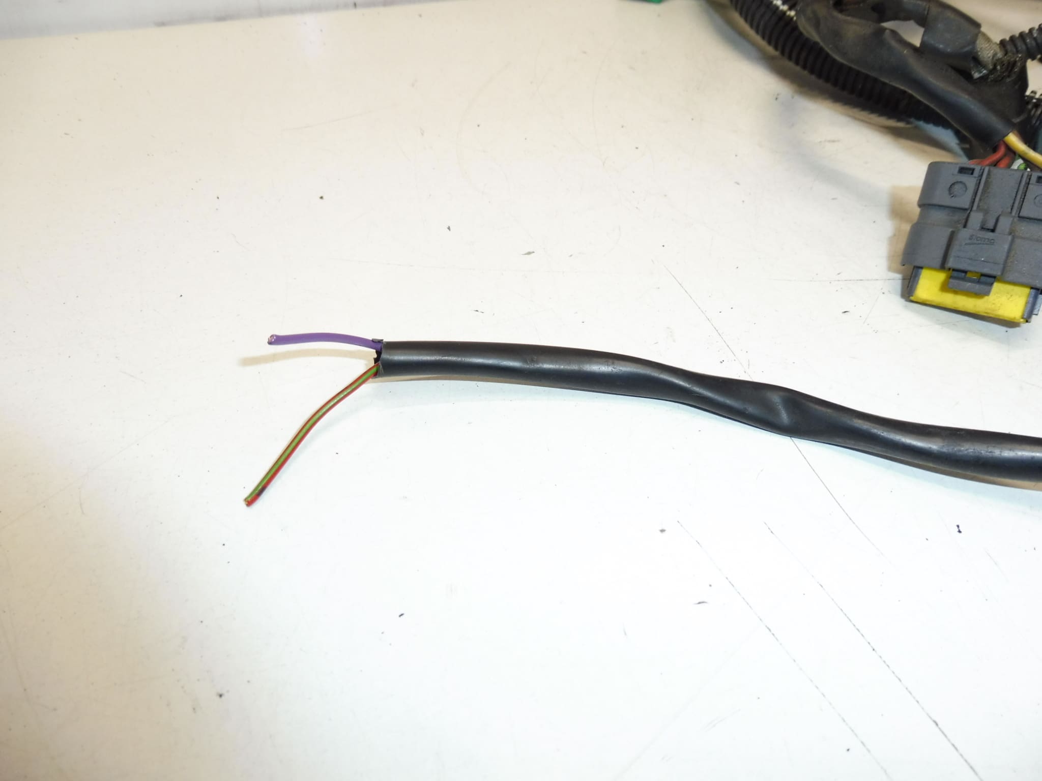
Engine wiring harness Citroën Peugeot 2.0 16V 130 kW RFK From 2004 Peugeot 307 CC. One two-wire connector is missing (see second photo).
This engine wiring harness is designed for Citroën and Peugeot 2.0 16V RFK engines producing 130 kW. The harness routes power and signal circuits for ignition coils, injectors, sensors and engine control modules, providing the critical electrical backbone for engine management. Ideal for professional workshops and experienced DIY mechanics who search by part number or engine code, this harness helps restore reliable engine operation when the original wiring is damaged or degraded. Note the missing two-wire connector shown in the photos — the harness is supplied as pictured and may require a replacement connector or professional repair to achieve full functionality.
Technical Information
- Manufacturer: Stellantis / Citroën / Peugeot
- Model: Peugeot 307 CC (2004) – Engine Code RFK, 2.0 16V, 130 kW
- Product Codes: 9651728880, 9659205180
- Other Numbers: 6558WG, NFP
- Function: Main engine wiring harness for sensors, ignition coils, fuel injectors and ECU connections (12 V vehicle electrical system)
Installation Recommendations
Before starting, disconnect the vehicle battery to avoid short circuits. Typical replacement steps:
- Remove engine covers, air intake components or battery tray as needed to access harness routing.
- Label and photograph all connector positions to ensure correct reconnection.
- Unplug sensors, ignition coils and ECU connectors, releasing any retaining clips and bracket bolts.
- Feed the new harness along the original routing, secure with factory clips or equivalent fasteners, and ensure no wires rub against sharp edges or hot components.
- Replace the missing two-wire connector with a matching OEM connector or an appropriate high-quality aftermarket equivalent; ensure correct pin assignment and use dielectric grease to prevent corrosion.
- Reconnect the battery and perform a full electrical check and engine scan for fault codes. Verify sensor readings and idle stability before road testing.
Why This Part Most Often Fails
- Heat and oil contamination leading to insulation degradation near the engine and exhaust areas.
- Mechanical wear from vibration and chafing where the harness contacts brackets or sharp edges.
- Connector corrosion or broken terminals, especially in moisture-prone locations.
- Rodent damage or accidental cuts during previous repairs.
- Stress and cracking at flex points or near connectors after many years of service.
Common fitment examples: Peugeot 307 (including 307 CC) with 2.0 16V RFK engine. Similar harness variants appear on some Citroën and Peugeot models using the RFK engine, but always confirm compatibility by matching the engine code and the product numbers listed above. The harness is delivered as photographed; the missing two-wire connector must be addressed during installation.