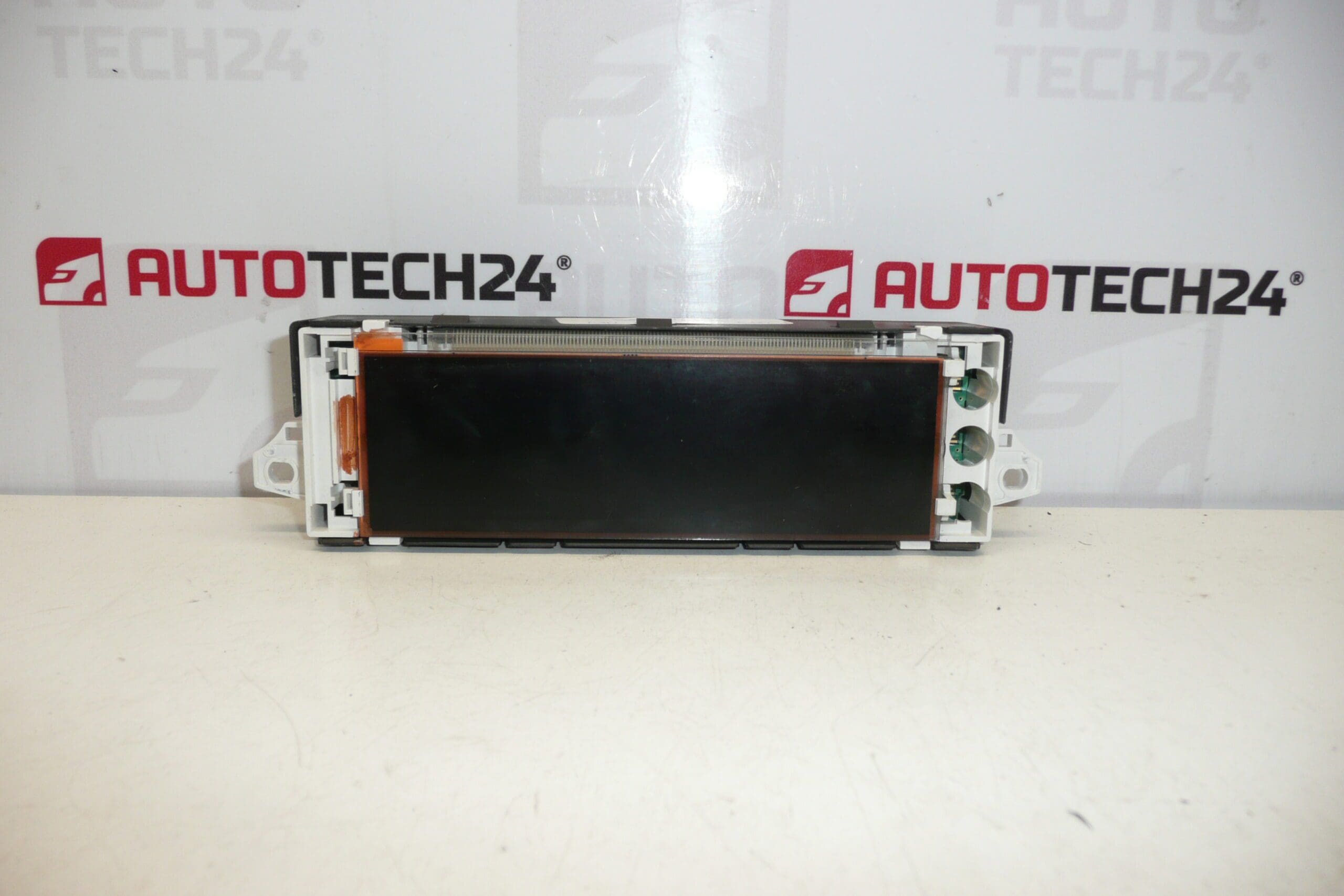
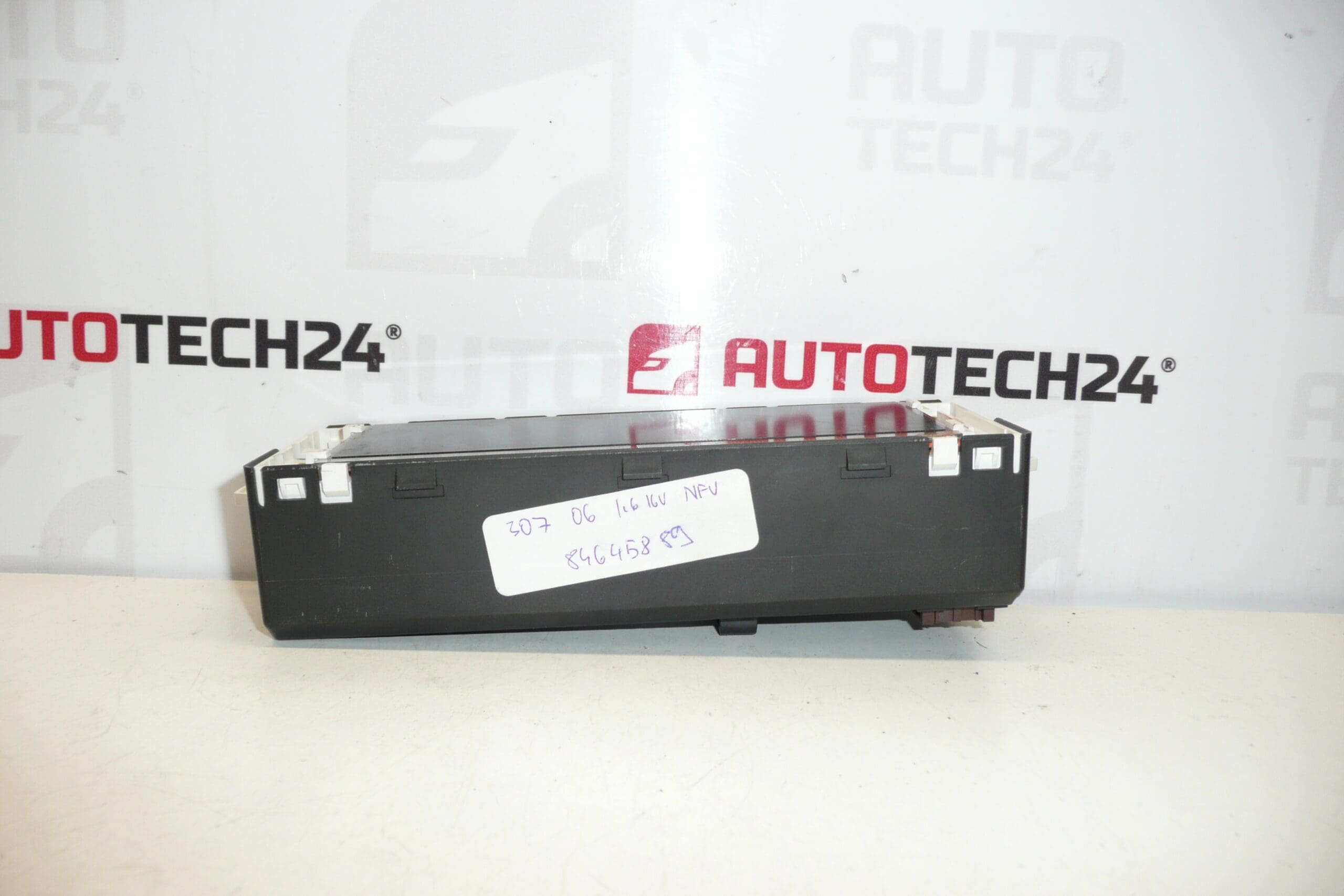
Description
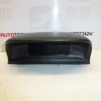
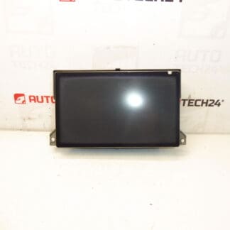
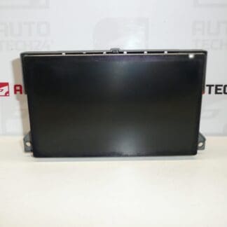
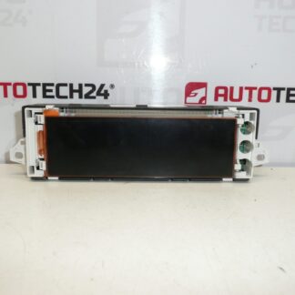
Radio and onboard computer display for PEUGEOT 307 vehicles from 2005. Some functions may need to be activated via diagnostic equipment.
Product Overview
Direct-fit replacement display for the radio and onboard computer used in Peugeot 307 (Phase 2) models. The unit displays radio information, trip computer data, clock, and basic vehicle messages. Ideal for mechanics and experienced DIYers who need a genuine OE-style interface and correct mounting geometry for the dash cluster.
Technical Information
- Manufacturer: Stellantis (Peugeot / Citroën)
- Model: Peugeot 307 (Phase 2) – from 2005
- Product Codes: 9660468480, 9822637880
- Additional Numbers: 6155CC, 6155CE
Compatibility
Fits Peugeot 307 Phase 2 models introduced in 2005. Typically used in common body styles for the 307 range; verify fitment by matching the product codes printed on the original unit. Some model variations and equipment levels may require software activation or configuration.
Functions And Typical Symptoms
The display Presents radio station and media information, trip computer readouts (range, fuel consumption, average speed), clock and basic vehicle messages. Common symptoms that indicate a faulty display include blank screen, faded or uneven backlight, vertical/horizontal lines, missing characters, intermittent operation and flickering.
Replacement Guide
- Disconnect the negative battery terminal before beginning to avoid short circuits and protect vehicle electronics.
- Carefully remove the dashboard trim around the radio cluster using plastic trim tools to prevent damage to clips and surrounding panels.
- Unscrew the radio/display mounting screws and gently pull the module forward to access connectors.
- Release the multi-pin connectors and any ribbon cables. Handle connectors by the plastic housing—do not pull on wires or flex the ribbon cable excessively.
- Install the replacement unit by reversing the removal steps. Ensure connectors are fully seated and trim clips align before final tightening.
- After installation, verify basic functions. Note that certain functions or messages may require diagnostic activation to enable full functionality.
Installation Recommendations
- Always Disconnect Battery Before Work. Protect The Vehicle’s Electrical System By Isolating The Battery.
- Use Non-Marring Trim Tools To Avoid Damage To Dash Surfaces.
- Observe ESD Precautions When Handling Electronic Modules To Reduce Risk Of Component Damage.
- Do Not Force Connectors Or Bend Ribbon Cables; Inspect Pins For Corrosion Or Damage Before Reassembly.
- If Features Remain Inactive After Mechanical Fitment, Activation Via PSA Diagnostic Tool (e.g., DiagBox/Lexia) May Be Required.
Why This Part Most Often Fails
Failures Are Usually Caused By Age-Related Degradation (Backlight And LCD Wear), Thermal Stress From Repeated Heating/Cooling Cycles, Moisture Ingress Or Condensation Leading To Corrosion On Connectors, And Poor Electrical Supply (Voltage Spikes Or Loose Grounding). Mechanical Impact Or Damage During Previous Repairs Can Also Cause Display Malfunction.
Service Life And Notes
Typical Service Life For These Displays Is Several Years; Many Units Last 8–15 Years Depending On Usage, Environmental Exposure And Vehicle Maintenance. If The Unit Shows Intermittent Behavior, Inspect Connectors, Ground Points And Power Supply Before Replacing The Entire Module.