Description
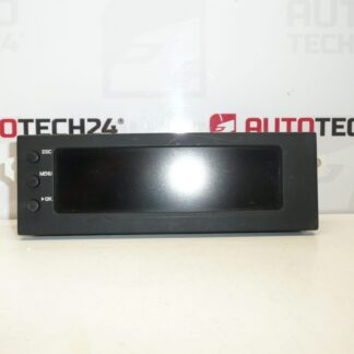
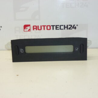
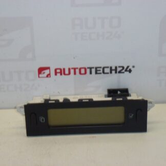
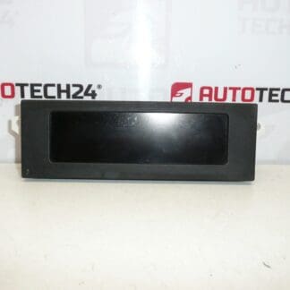
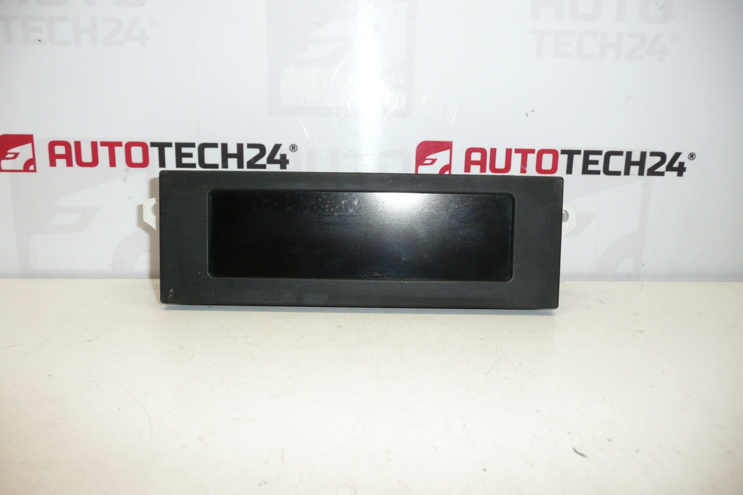
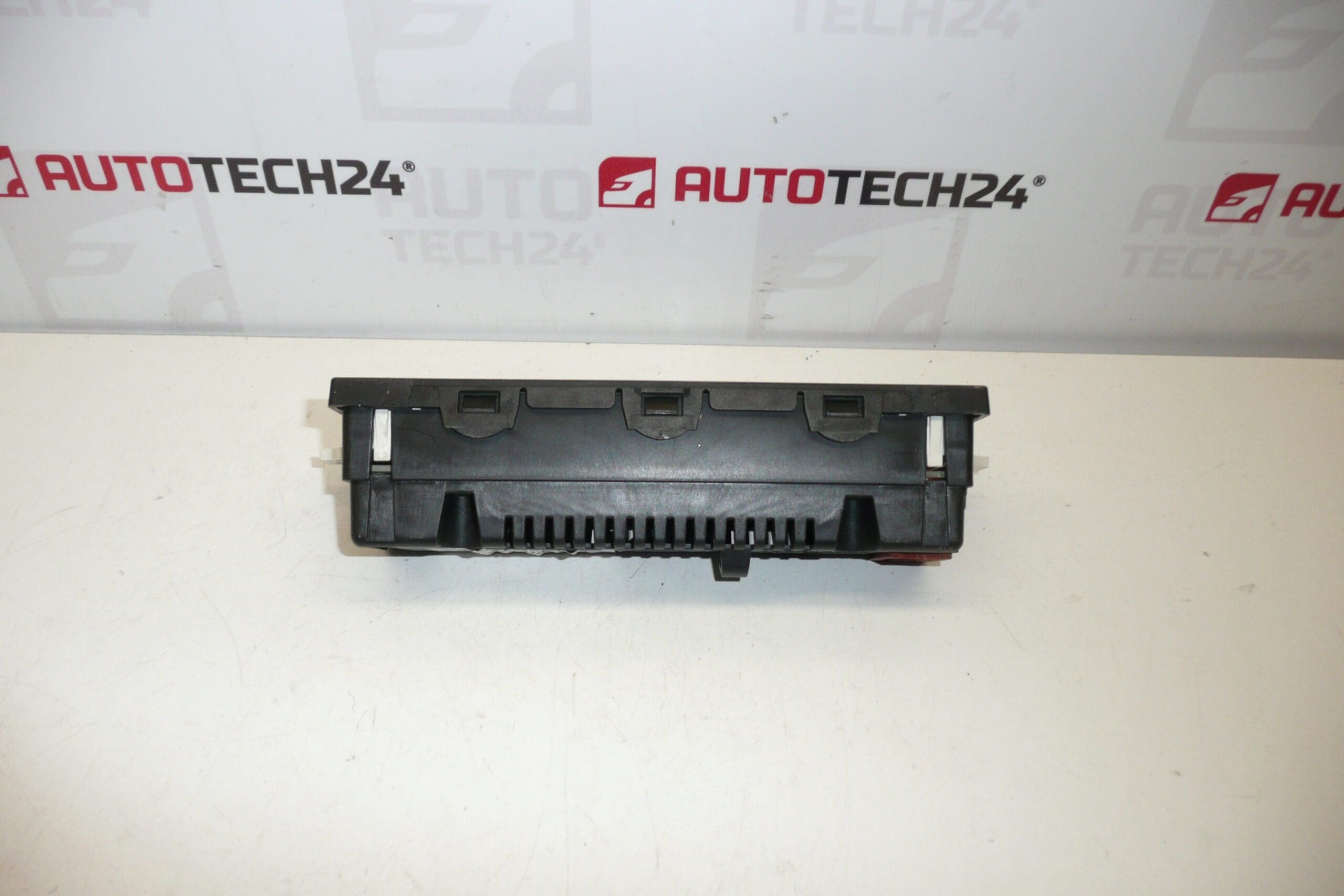
Radio and trip computer display for Citroën C2, C3 and C3 Pluriel vehicles from 2005. Some functions may need activation via diagnostics.
Product Overview
Replacement display for the radio and onboard trip computer, suitable for Citroën C2, C3 and C3 Pluriel models. This unit is commonly referenced under product codes 96597970XT, 9822637880 and 6155EX. It restores visual information such as radio station, clock, mileage/trip data and menu prompts, and is aimed at professional workshops and competent DIYers performing dashboard or radio repairs.
Compatibility And Application
Designed to fit the original instrument/radio housing used on listed Citroën models. Mechanical fitment is direct in the compatible dashboards, but some functions or menu items may require diagnostic activation or coding to match the vehicle’s configuration. Ideal for vehicles where the original display has failed, dimmed, shows missing segments, or suffers from backlight issues.
How The Part Is Replaced (General Guide)
1) Disconnect the vehicle battery before starting work to prevent short circuits and protect electronics.
2) Remove surrounding trim and radio bezel to access the display assembly.
3) Unscrew retaining screws and carefully unplug the display ribbon/connector(s). Note position of any brackets or spacers.
4) Install the replacement display by reversing removal steps, reconnect connectors firmly and test all functions before reassembly.
5) If certain features do not appear, diagnostic activation or coding may be required.
Technical Information
- Manufacturer: Stellantis (Citroën)
- Model: Citroën C2, Citroën C3, Citroën C3 Pluriel (from 2005)
- Product Codes: 96597970XT, 9822637880, 6155EX
- Additional Numbers: OEM / Supplier reference numbers as listed above
Installation Recommendations
Always disconnect the battery before removing the dashboard components. Handle the LCD and flex cables with care to avoid creases or tears. Avoid excessive force on connectors; use appropriate trim tools to prevent damage to plastic bezels. When reassembling, verify seating and connector engagement, and perform a functional check of display illumination and menu navigation. If activation or feature coding is needed, use the appropriate PSA diagnostic equipment or have a qualified technician perform the coding.
Most Common Failure Modes And Causes
Displays typically fail due to backlight degradation (LED or electroluminescent panel), failing solder joints from thermal cycling, moisture ingress and corrosion at connectors, cracked or damaged flex ribbon cables, or internal power supply/filter component faults. Visible symptoms include partial or full loss of segments, dim backlight, flickering, or intermittent operation.
Why Choose This Replacement
Replacing a faulty display restores clear, reliable readout of radio and trip computer information and avoids the need for more invasive dashboard repairs. Including the product codes 96597970XT, 9822637880 and 6155EX in your search or workshop order helps quickly identify the correct unit for the listed Citroën models.