Description
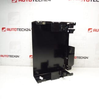
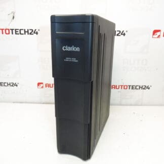
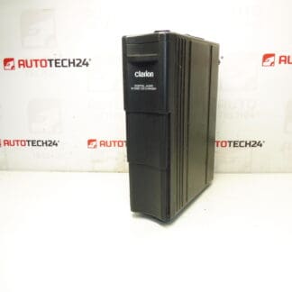
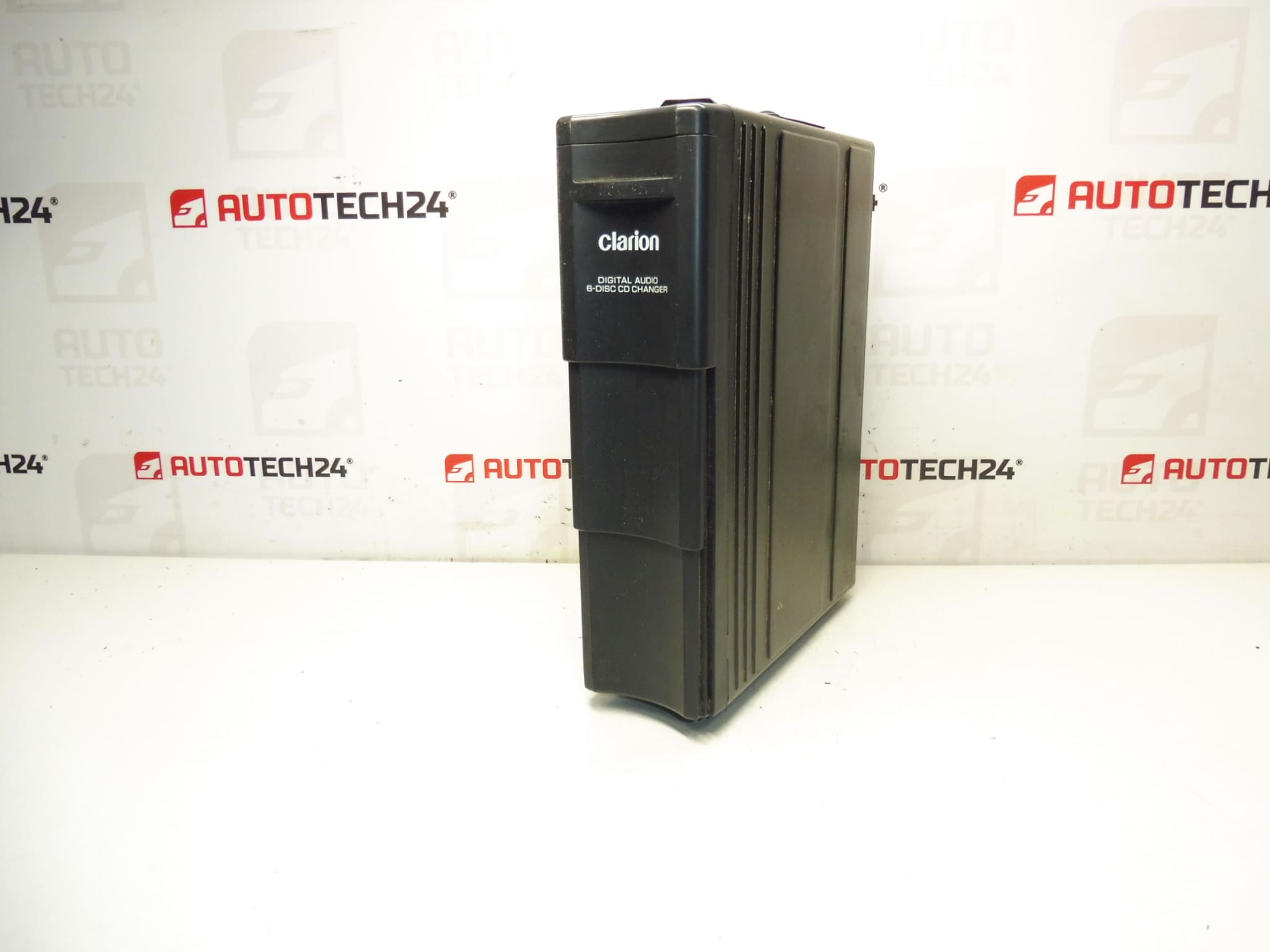
Clarion CD changer for CITROËN C5 from 2005. Tested; delivery includes CD magazine. Bracket can be purchased under code 6560Q4. Connection harness can be purchased under code 6560XR.
This Clarion CD changer is an OEM-compatible unit designed to restore original in-car audio functionality in Citroën C5 vehicles (II generation) from 2005 onwards. The unit is supplied with the CD magazine, making it ready for immediate use once mounted and connected. It is a practical replacement for worn or non-working factory CD changers and is suitable for professional workshops and DIY mechanics who prefer reliable, vehicle-specific parts. The Clarion unit keeps the original look and user experience of the factory audio system and is often searched by its product codes 9647427980 and 6564E1.
Technical Information
Manufacturer: Clarion
Model: Citroën C5 II (from 2005)
Product Codes: 9647427980, 6564E1
Additional Numbers: Bracket 6560Q4, Wiring Harness 6560XR
Features & Benefits
OEM-style fitment for factory audio systems, supplied with the CD magazine for immediate use. Maintains vehicle interior authenticity and plug-and-play operation when used with the correct OEM harness. Ideal for replacing units that no longer read discs, skip, or produce audio errors.
Installation Recommendations
Before starting, disconnect the vehicle battery to avoid electrical shorts. Remove the necessary trim or storage compartment to access the changer mounting location (refer to vehicle service manual for exact access points). Secure the changer using the dedicated bracket (code 6560Q4) if not already fitted. Use the OEM connection harness (code 6560XR) to connect the changer to the head unit; ensure all plugs are clean and fully seated. Route the cable neatly, avoiding sharp edges and heat sources, then reconnect the battery and test playback with multiple discs. Reassemble trim panels only after confirming correct operation.
Common Failure Causes
Most CD changer faults are caused by mechanical wear of the magazine and loading mechanism, degradation of the laser pickup over time, connector corrosion or poor grounding, moisture ingress, and intermittent wiring faults. Symptoms include failure to read discs, skipping during playback, audible mechanical noises, and error messages from the head unit. Age and heavy use accelerate wear of moving parts and the optical system.
Practical Notes For Mechanics and DIYers
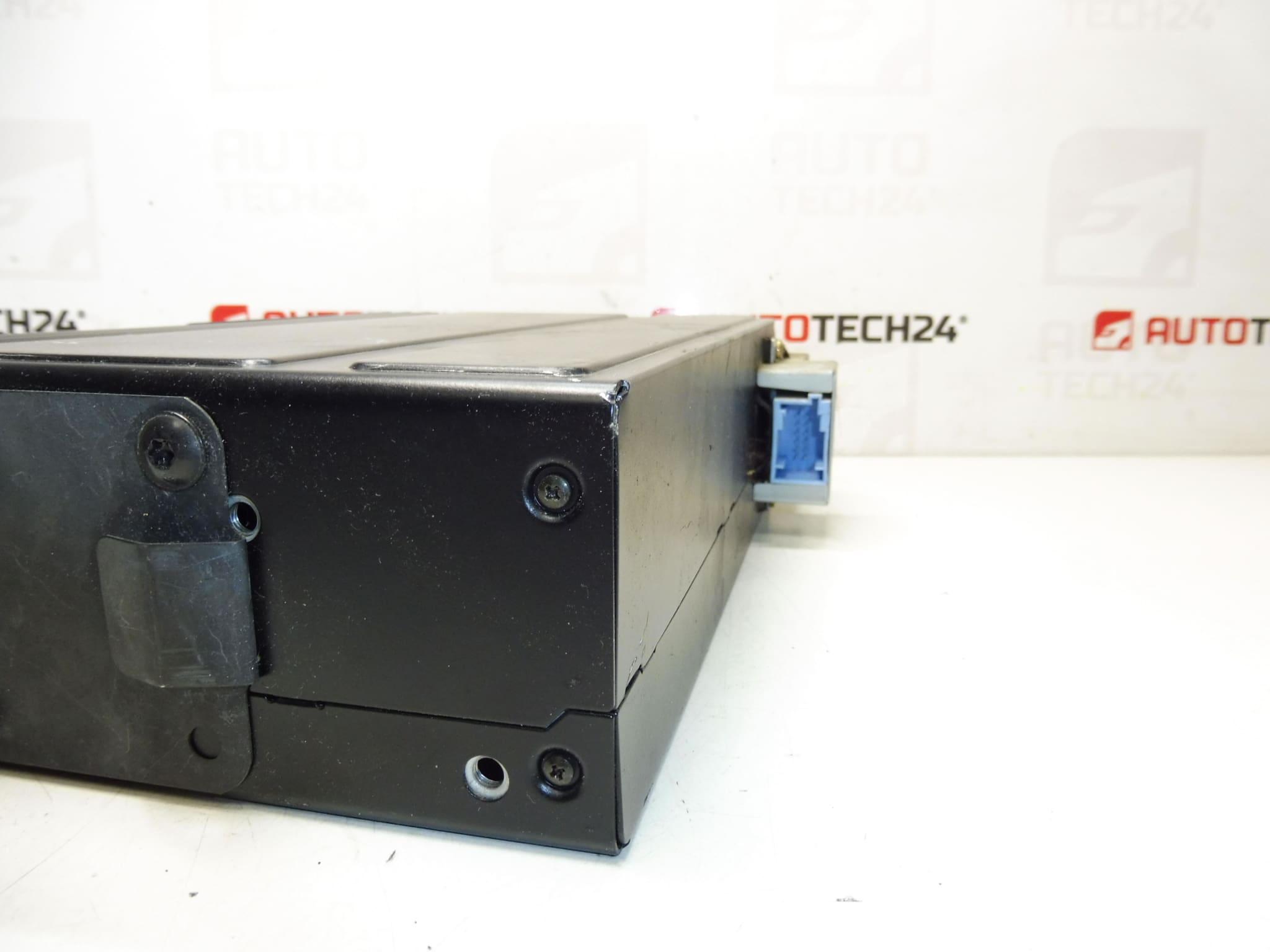
When replacing the changer, inspect the vehicle harness connectors and the head unit socket for corrosion or bent pins. If the unit powers up but does not read discs, cleaning the laser can sometimes restore function, but repeated failures typically indicate mechanical or optical wear that warrants replacement. Keep the CD magazine and discs dry and free of dust during installation to avoid read errors. If the bracket or harness is missing, order items 6560Q4 and 6560XR to ensure a secure and correct installation.
Why Choose This Part
This Clarion changer offers a straightforward solution to restore factory CD playback in compatible Citroën vehicles. Clear product codes (9647427980, 6564E1) improve findability for mechanics searching by reference, and the inclusion of the CD magazine adds immediate value for hands-on repairs.