Description
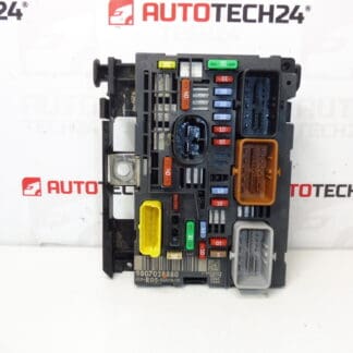
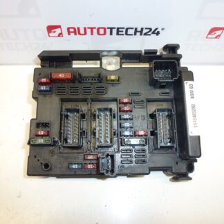
BSM B3 DELPHI for Citroën and Peugeot vehicles. Some mounting brackets may be damaged – does not affect functionality.
The BSM B3 Delphi module is the central engine-bay body module used on a number of Citroën and Peugeot models. Frequently searched by OE numbers 9646405280 and 6500Y1, this unit integrates power distribution, fuses and relays for many engine-bay and comfort circuits. It is suitable for professional workshops and experienced DIY mechanics who need a reliable replacement to restore electrical functions such as lighting, starter relay feed, wipers and other fused circuits controlled from the engine compartment.
Technical Information
- Manufacturer: Delphi
- Model: BSM B3 (Body System Module)
- Product Codes: 9646405280, 6500Y1
- Other Numbers: BSM B3
- Compatible Vehicles: Citroën Xsara, Citroën Xsara Picasso, Peugeot 206 (check specific vehicle year/variant against part number)
Function And Typical Symptoms
The BSM manages several engine-bay electrical circuits via integrated fuses and relays. When the BSM develops a fault you may observe intermittent or permanent loss of functions such as external lighting, starter relay operation, fuel pump relay activation, windscreen wipers, or unexpected blown fuses. Faults can present as complete failure of multiple circuits or as sporadic electrical issues that depend on vibration or temperature.
Why The Part Commonly Fails
- Water Ingress And Corrosion: Exposure to moisture in the engine bay or degraded seals can corrode contacts and PCB traces.
- Electrical Overload Or Short Circuits: Repeated overloads or short circuits can damage relays and solder joints inside the module.
- Thermal Stress And Ageing: Heat cycles accelerate deterioration of electronic components and connectors over many years.
- Connector And Wiring Damage: Damaged pins, poor grounding or loose connectors cause intermittent faults that mimic module failure.
- Mechanical Damage To Mounting Brackets: As noted, plastic brackets can be broken without affecting electronic function, but secure mounting is recommended.
How To Replace
- Prepare: Park vehicle on a flat surface, engage parking brake and remove any load on the electrical system.
- Disconnect Battery: Always disconnect the negative battery terminal before starting to avoid short circuits and protect electronic components.
- Access Module: Locate the BSM in the engine bay (usually under a protective cover near the battery or left fender). Remove the cover and any retaining screws or clips.
- Release Connectors: Carefully unlock and remove the multi-pin connectors by releasing the retention clips. Note connector orientation and locking tabs.
- Unbolt Module: Remove mounting screws or bolts and extract the module. Inspect mating connectors and wiring for corrosion or damage.
- Install Replacement: Fit the new module, secure mounting hardware and reconnect all connectors ensuring full engagement of locking clips.
- Reconnect Battery And Test: Reconnect negative battery terminal and test all relevant circuits (lighting, starter relay, wipers, etc.). Verify fuses and relays function correctly.
Installation Recommendations
- Always Disconnect The Battery Before Removal Or Installation To Prevent Damage.
- Inspect Connectors And Wiring Harness For Corrosion Or Heat Damage; Repair Faulty Wiring Before Installing The Module.
- Ensure Module Is Firmly Secured To Avoid Vibration-Induced Connector Problems.
- Replace Any Brittle Or Damaged Mounting Brackets To Prevent Future Mechanical Stress.
- After Installation, Perform A Full Functional Check Of All Related Circuits And Read Fault Codes With An Appropriate Diagnostic Tool.
Service Life And Maintenance
Lifespan Depends On Vehicle Use And Environmental Conditions. Modules Often Last Many Years Under Normal Conditions; However Longevity Drops If The Engine Bay Is Exposed To Moisture, Road Salt Or Repeated Electrical Faults. Regular Inspection Of Connectors And Sealing Areas Helps Prevent Failures.
Additional Notes
This BSM is commonly listed under the OE reference numbers given above. Some physical mounting tabs or brackets may be damaged without affecting electrical performance; nevertheless, secure mounting is important to prevent connector stress. If electrical problems persist after replacement, verify wiring, grounds and fuses before assuming module failure.