Description
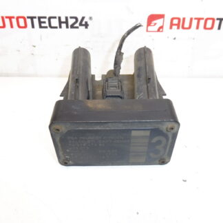
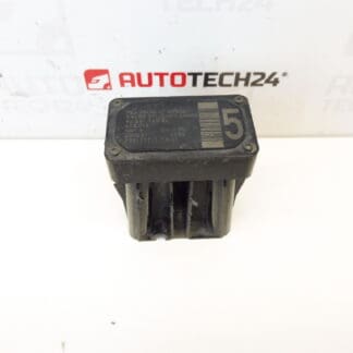
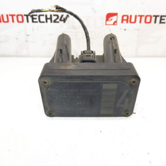
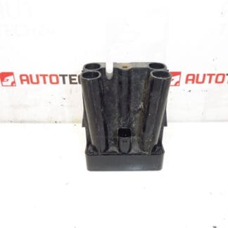
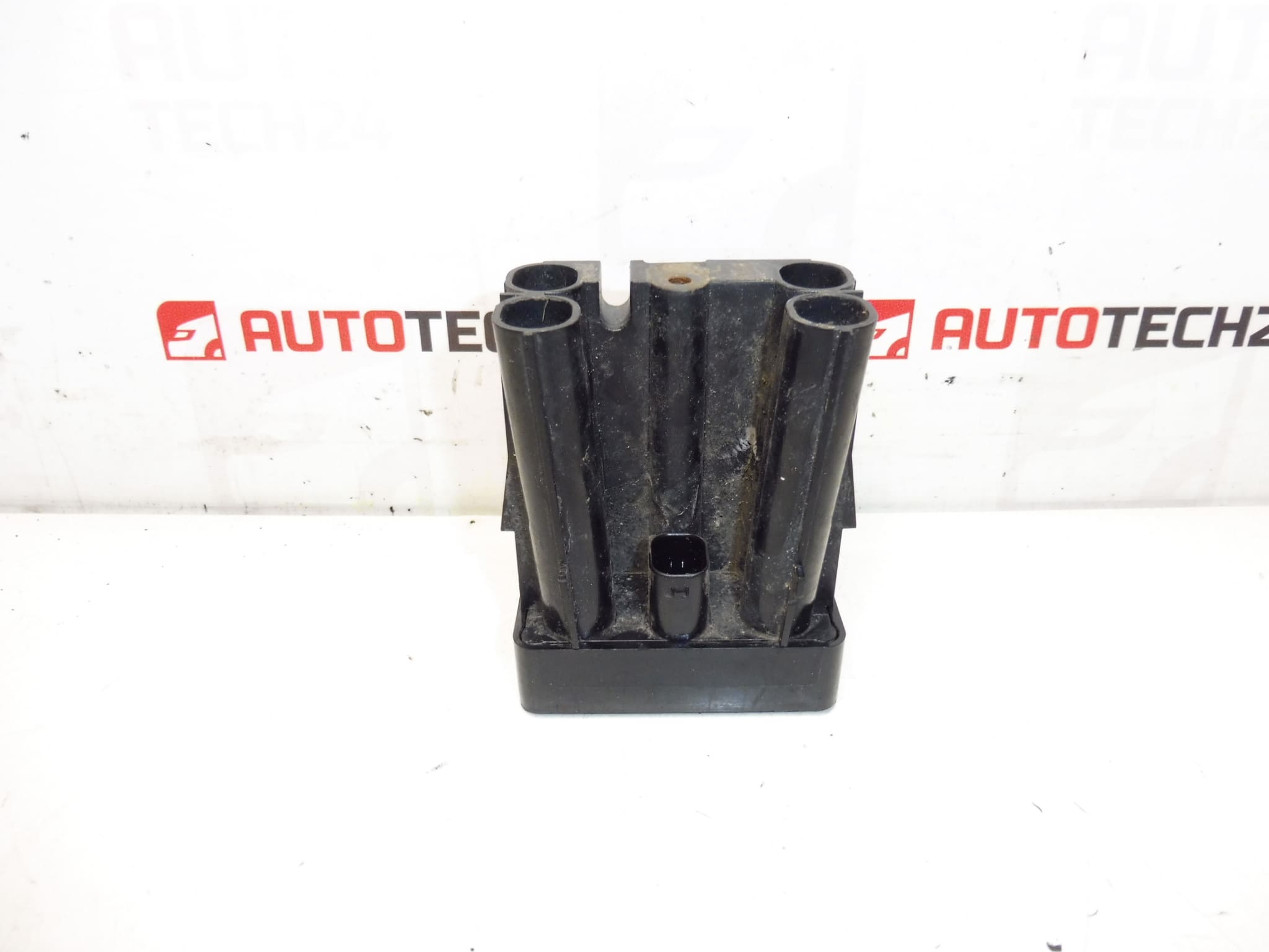
AFIL lane monitoring sensor number 2 for Citroën and Peugeot vehicles. A screw that secures the unit to the wheel arch may be seized — drilling out may be necessary.
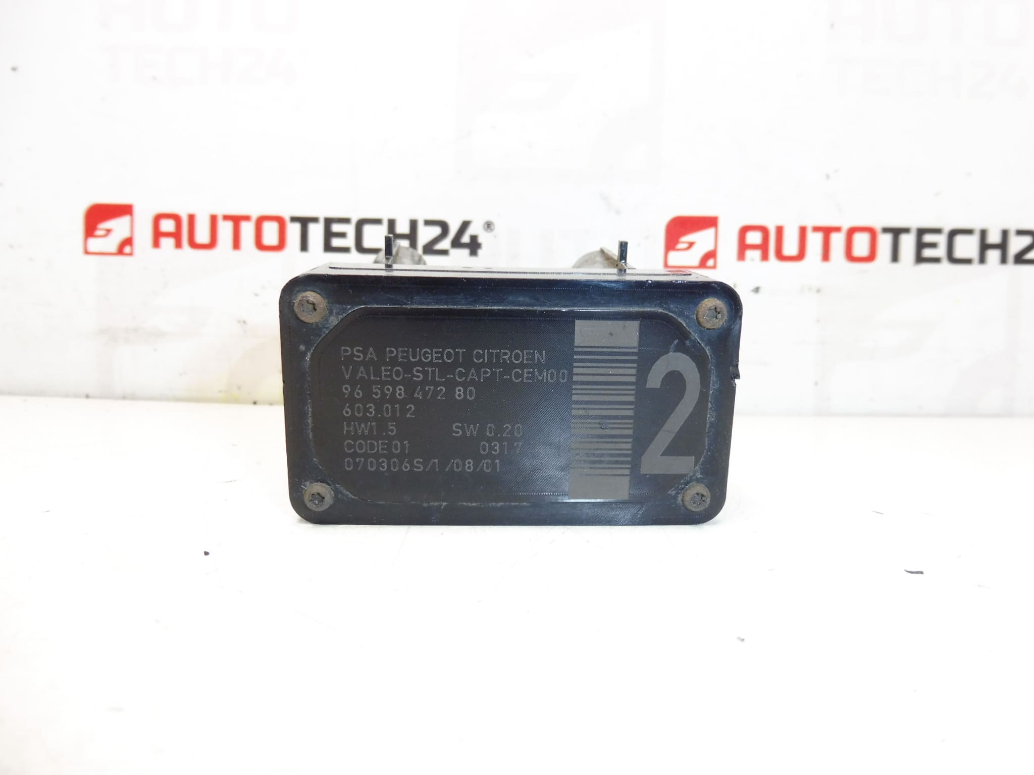
This AFIL (lane monitoring) sensor is a direct-fit component for a range of Citroën and Peugeot models and is commonly identified by OE numbers 9659847280, 6590W1 and catalogue reference 603.012. Designed for professional workshops and competent DIY mechanics, this sensor restores lane-monitoring functions after collision damage, corrosion or electrical faults. Searching by part number (e.g. 9659847280 or 6590W1) will quickly locate the correct item for compatible vehicles.
Technical Information
- Manufacturer: Stellantis
- Model: Citroën C4, Citroën C4 Picasso, Citroën C5, Citroën C5 X7, Citroën C6, Peugeot 308, Peugeot 407
- Product Codes: 9659847280, 6590W1
- Additional Numbers: 603.012
Function
The AFIL sensor is part of the lane monitoring / lane-keeping assistance system. It detects lane markings and provides data to the vehicle’s ADAS control unit to warn the driver or support corrective steering interventions. Proper operation depends on an intact sensor, secure mounting and an undamaged electrical connection.
Installation Recommendations
Before starting work, isolate the vehicle battery to avoid electrical faults. Access the sensor via the wheel arch liner or inner wing trim; on many models the unit is fastened to the wheel arch. Remove surrounding trim and any obstructing components to reach the sensor. If the mounting screw is seized or corroded, it may need to be drilled out as noted in the original description—replace any damaged fasteners with new hardware and treat exposed threads with an appropriate anti-corrosion compound. Unplug the electrical connector carefully and inspect for corrosion or bent pins. Fit the new sensor in the correct orientation, secure the mounting, reconnect the electrical connector and reassemble trims. After replacement, run a system check and perform ADAS calibration if the manufacturer’s service procedure requires it.
Most Common Reasons For Failure
Typical causes of AFIL sensor faults include impact damage (minor collisions or curb strikes), water ingress and corrosion at the connector or mounting, mechanical shock, or damaged wiring from road debris. A seized or corroded mounting screw is a frequent physical issue that can complicate removal and is specifically noted for this part.
Notes For Buyers
Searchable by OE numbers 9659847280 and 6590W1. Suitable for the listed Citroën and Peugeot models above. Ensure the sensor’s part number matches your vehicle’s requirement before ordering; this product is aimed at trained technicians and experienced DIYers familiar with ADAS components and calibration procedures.