Description
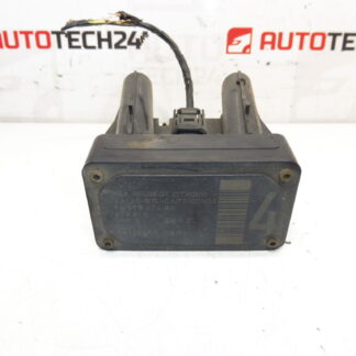
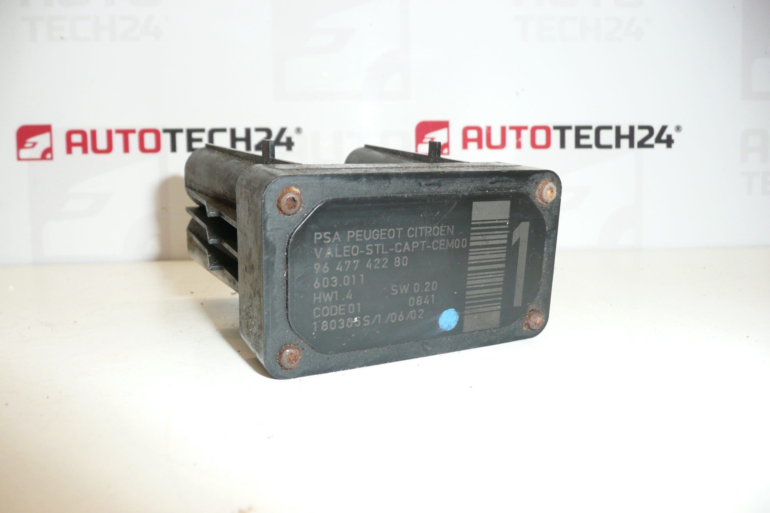
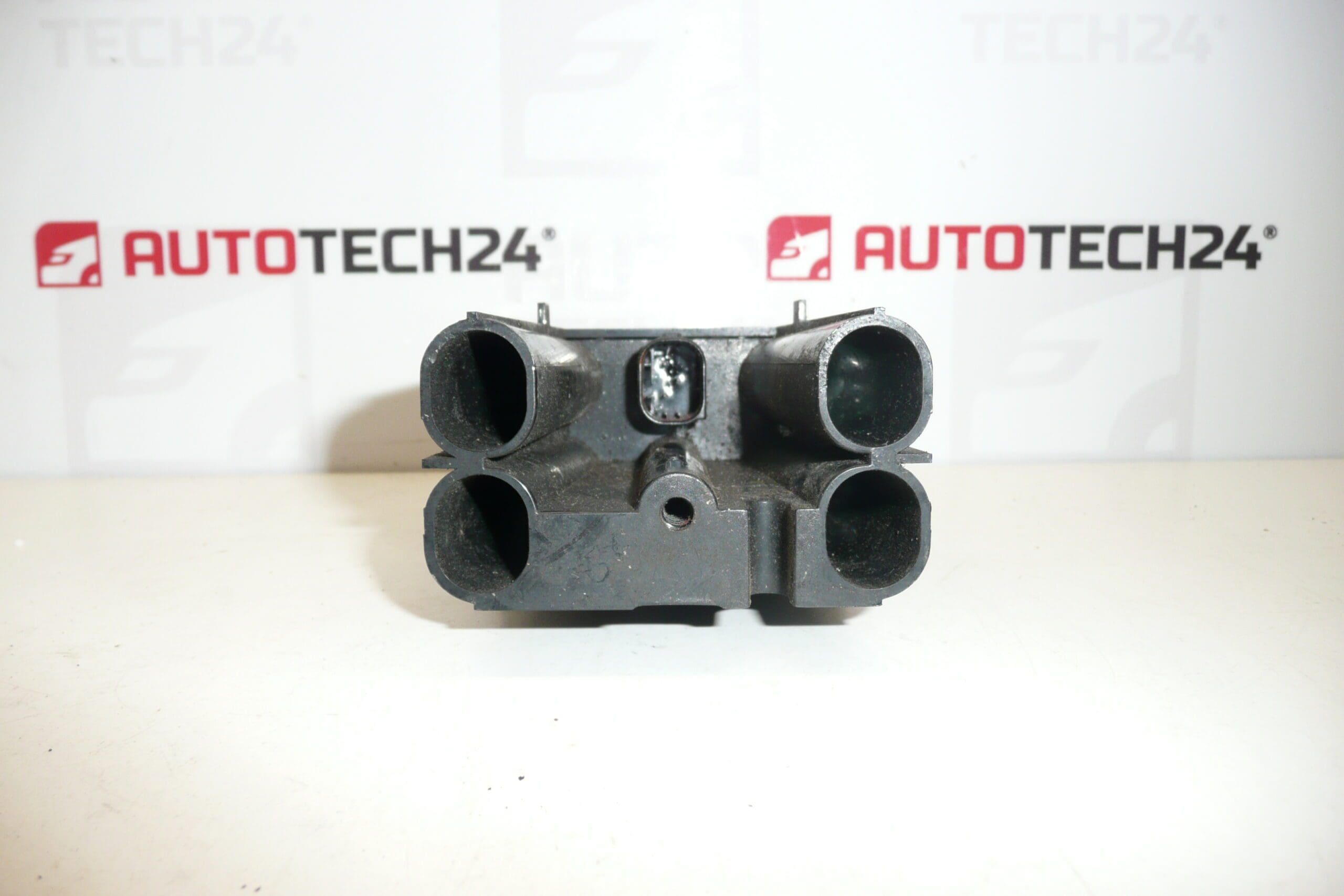
AFIL lane-monitoring sensor number 1 for Citroën and Peugeot vehicles. A screw that secures the unit to the inner wheel arch may be seized or sheared — drilling out may be necessary.
The AFIL (Lane Departure Warning / Lane Keeping) sensor is a direct-fit replacement part designed for several Citroën and Peugeot models. This electronic sensor supplies the vehicle’s driver-assist system with lane-position information and helps trigger warnings or corrective actions when the car drifts from its lane. Technically minded buyers and professional technicians often search for this part by its product code (e.g. 9647742280), so listing the reference will speed up identification and ordering.
Technical Information
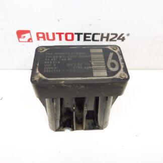
- Manufacturer: Stellantis (Citroën/Peugeot)
- Model: Citroën C4; Citroën C4 Picasso; Citroën C5; Citroën C5 X7; Citroën C6; Peugeot 308; Peugeot 407
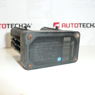
- Product Codes: 9647742280; 603.011; 6590W1
- Additional Numbers: AFIL Sensor 1; Category: AFIL | Electrical Components | Sensors | Detectors
Key Features & Benefits
- Direct replacement for factory AFIL lane-monitoring sensors on listed Citroën and Peugeot models.
- Restores lane-departure warning function and lane-keeping assistance to OEM performance (when correctly installed and calibrated).
- Commonly searched by OE number 9647742280 — convenient for quick identification in parts catalogs.
- Robust electrical connector and mounting design; however, mounting hardware can corrode or shear over time.
Installation Notes
Recommended for fitters and experienced DIY mechanics. Typical replacement steps:
- Disconnect the vehicle battery before starting any work on electronic components to avoid short circuits.
- Gain access to the unit location (inner wheel arch / mounting point). In many models it is necessary to remove the wheel or inner splash guard for safe access.
- Unplug the electrical connector and remove the mounting screws. Note: A seized or sheared screw is a common issue on these units — drilling out the fastener may be required.
- Fit the replacement sensor, secure with correct fasteners, reconnect the electrical connector and reassemble removed parts.
- Power up the vehicle and perform any required system initialization or calibration procedures as specified by the manufacturer or service manual (ADAS/driver-assist systems commonly require confirmation/calibration after sensor replacement).
Why This Part Fails (Most Common Causes)
- Water ingress / corrosion of connectors and contacts leading to intermittent or permanent electrical failure.
- Impact or mechanical damage from road debris or minor collisions.
- Seized, stripped or sheared mounting screws where the unit attaches to the inner wheel arch, making removal and service difficult.
- Internal electronic faults caused by age, thermal stress or manufacturing defects.
Advice for Fitters
- Always have the correct removal tools available (penetrating oil, extractor drills and screw drills) if mounting screws are seized.
- Inspect mating connectors and wiring harness for corrosion or damage before fitting the new unit; replace or repair harness components if necessary.
- Follow manufacturer service procedures for calibration or system reset to ensure proper operation of lane-keeping and warning functions.
- Record the OE product code (9647742280) when ordering or stocking parts to reduce the risk of incorrect replacements.
This replacement AFIL sensor is aimed at professional mechanics and competent DIY enthusiasts who maintain Citroën and Peugeot vehicles. The presence of the OE number in the description helps customers find the correct part quickly in search engines and parts databases.