Description
Battery state-of-charge unit for CITROEN, PEUGEOT and other Stellantis models
Part description
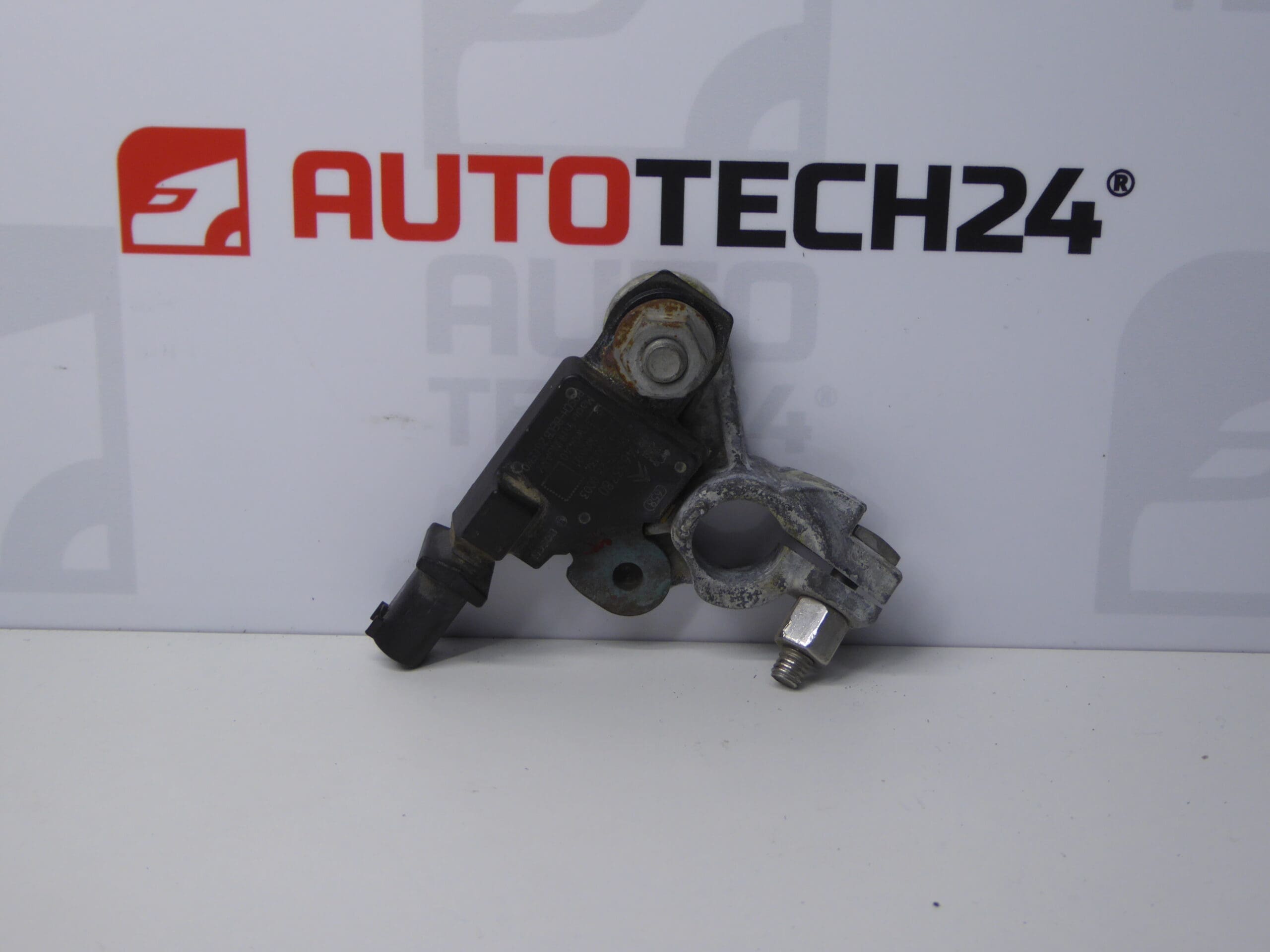
The used battery state-of-charge unit 9814653780 is designed to monitor the battery’s state. For this type of part, the data collected is used to manage the vehicle’s electrical energy. The unit therefore needs to function correctly to assess the battery’s condition and manage the available electrical energy.
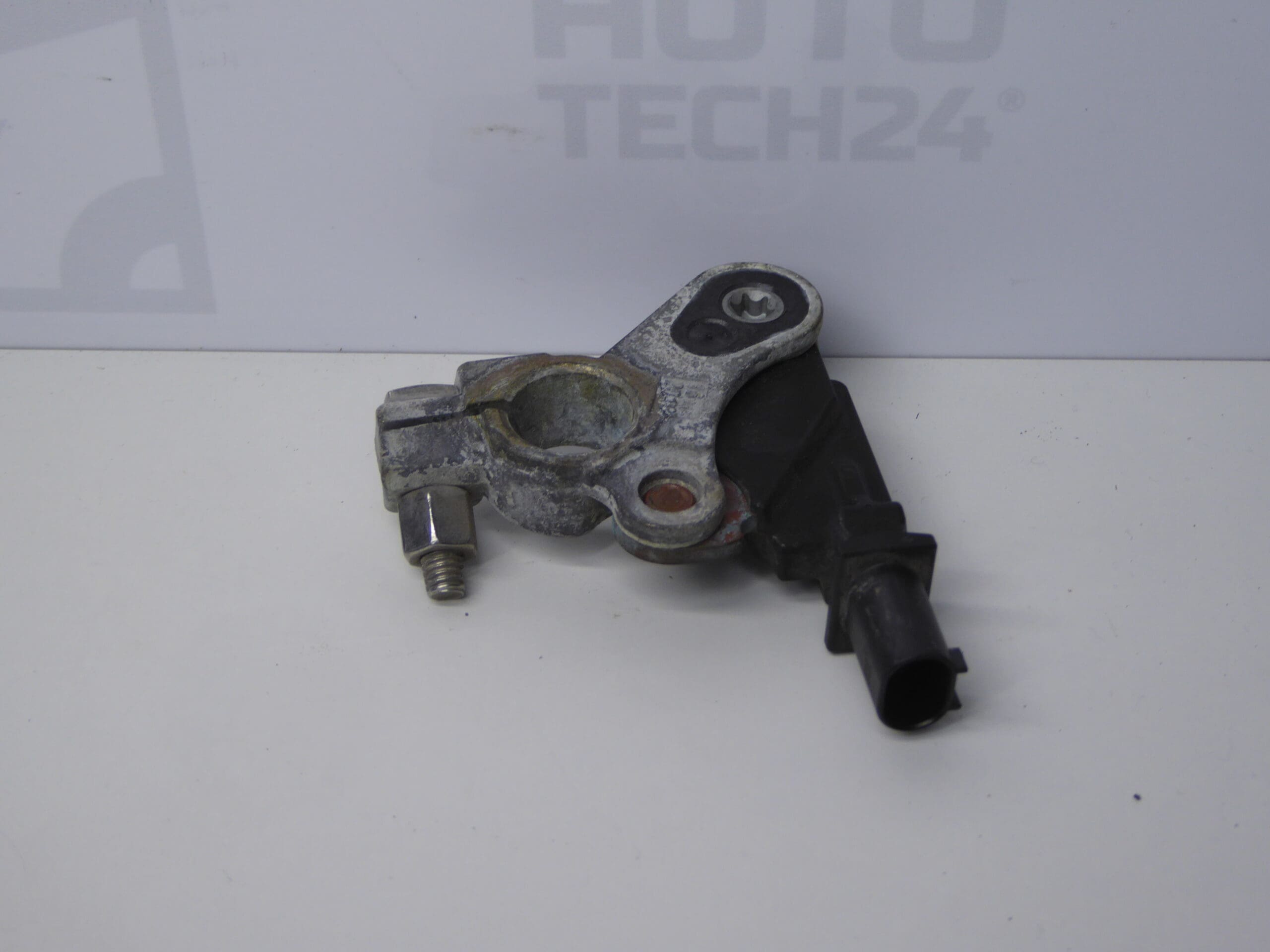
When looking for a replacement part, focus primarily on product number 9814653780 and ensure that the design matches the original unit. A used part is a cost-effective option for replacing a faulty component. However, a matching model name alone is not enough to determine whether it is suitable for a specific vehicle configuration.
Technical information
- Manufacturer: not specified
- Model: Citroën Berlingo K9; FIAT DOBLO III; OPEL COMBO E K9; Peugeot 308 T9; PEUGEOT RIFTER; Toyota ProAce City
- Part type: battery state-of-charge unit
- Condition: used part
- Other numbers: not specified
The models are taken from the supplied labels. The information provided does not specify model years, engine variants or electrical equipment configurations.
Product codes
- Product codes: 9814653780
Compare the number with the marking on the removed part. Also check the connectors, mounting points and overall design of the unit.
Installation recommendations
The following procedure is a general guide to replacing an electrical unit that monitors battery condition. The precise steps, power disconnection method and any required service procedures depend on the specific model and vehicle configuration. Follow the manufacturer’s service documentation.
1) Before installation
- Compare the part number, housing shape, mounting points, connectors and contact arrangement with the old part.
- Inspect the used unit: it should not have a cracked housing, damaged contacts, loose connections or visible signs of moisture or overheating.
- Check the condition of the battery, wiring and electrical connections. Similar symptoms may also be caused by a fault outside the unit itself.
2) Tools and materials required
- Standard hand tools suitable for the fasteners used.
- Suitable tools for gently releasing connector locks and any covers.
- Protective gloves, eye protection and products for safely cleaning electrical connections, if cleaning is required.
- A suitable measuring instrument and diagnostic equipment that supports the vehicle in question, for confirming the fault and verifying the final operation.
3) Step-by-step installation procedure
- Park the vehicle safely, switch off the ignition and turn off electrical accessories.
- Following the manufacturer’s procedure, allow the electronic systems to enter sleep mode and safely disconnect the battery. Prevent the power supply from being accidentally restored.
- Access the unit as described in the service documentation. Remove any covers without using force.
- Record the original wiring route and connection orientation, for example by taking a photograph.
- Release the connector locks and disconnect the connections. Do not pull on the wires or short the contacts with tools.
- Release the mountings and remove the original unit without damaging the surrounding wiring.
- Inspect the seating and mounting points and the mating connector parts. Repair any corrosion or damaged connections before installing the replacement part.
- Position the replacement unit, secure it according to the manufacturer’s instructions and connect the connectors, ensuring they are properly locked in place.
- Return the wiring and covers to their original positions. Check that the wires are not stretched, pinched or exposed to abrasion.
- Restore the power supply according to the manufacturer’s procedure. If the service documentation specifies initialization or another diagnostic procedure, carry it out.
4) Post-installation checks and function verification
Check that the unit is securely mounted and all connections are properly locked in place. Use suitable diagnostic equipment to verify communication and the available data related to battery monitoring. Check for any warning messages. If everything is in order, carry out a short test drive and then inspect the system again; the warning message going out on its own does not necessarily confirm that the cause of the fault has been resolved.
5) Common installation errors and how to avoid them
- Confusing similar units: compare the markings and physical design, not just the vehicle model.
- Working with the power on: follow the prescribed procedure for disconnecting and reconnecting the battery.
- Damaging connectors: release the locks first and do not use excessive force.
- Overlooking faulty wiring or a faulty battery: check the related parts of the electrical system before replacing the unit.
Reasons why the part gets damaged
In general, this type of electrical part may be damaged or fail to function correctly due in particular to:
- Moisture and corrosion on the contacts, which impair the electrical connection.
- Voltage spikes, a short circuit or incorrect handling when connecting the battery.
- Mechanical stress on the housing, connectors or attached wires.
- Vibration, temperature stress and gradual ageing of electronic components.
- Loose or damaged electrical connections in the associated wiring.
Before replacing the part, it is advisable to also eliminate the cause of the original fault to prevent damage to the replacement unit.