Description
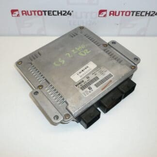
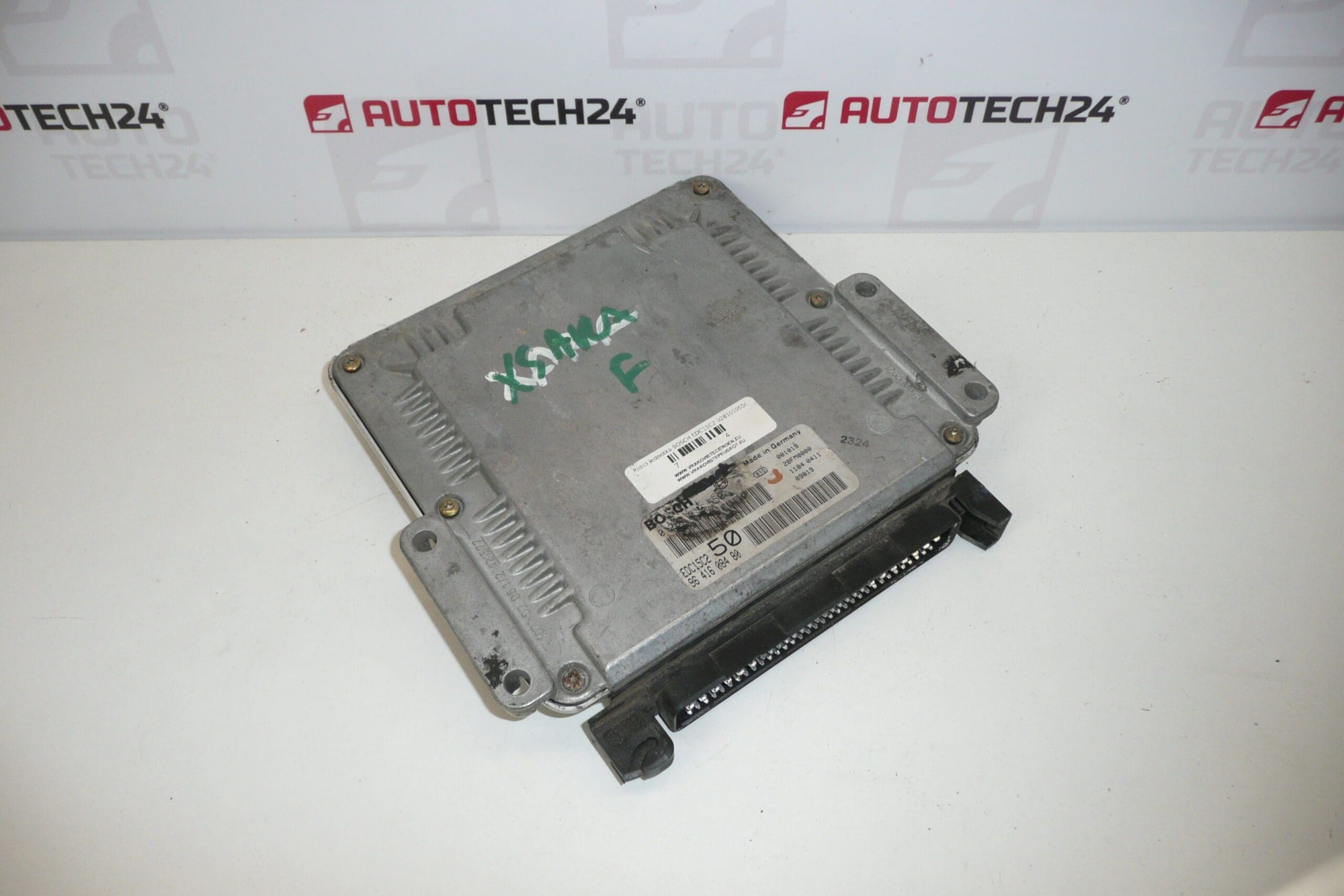
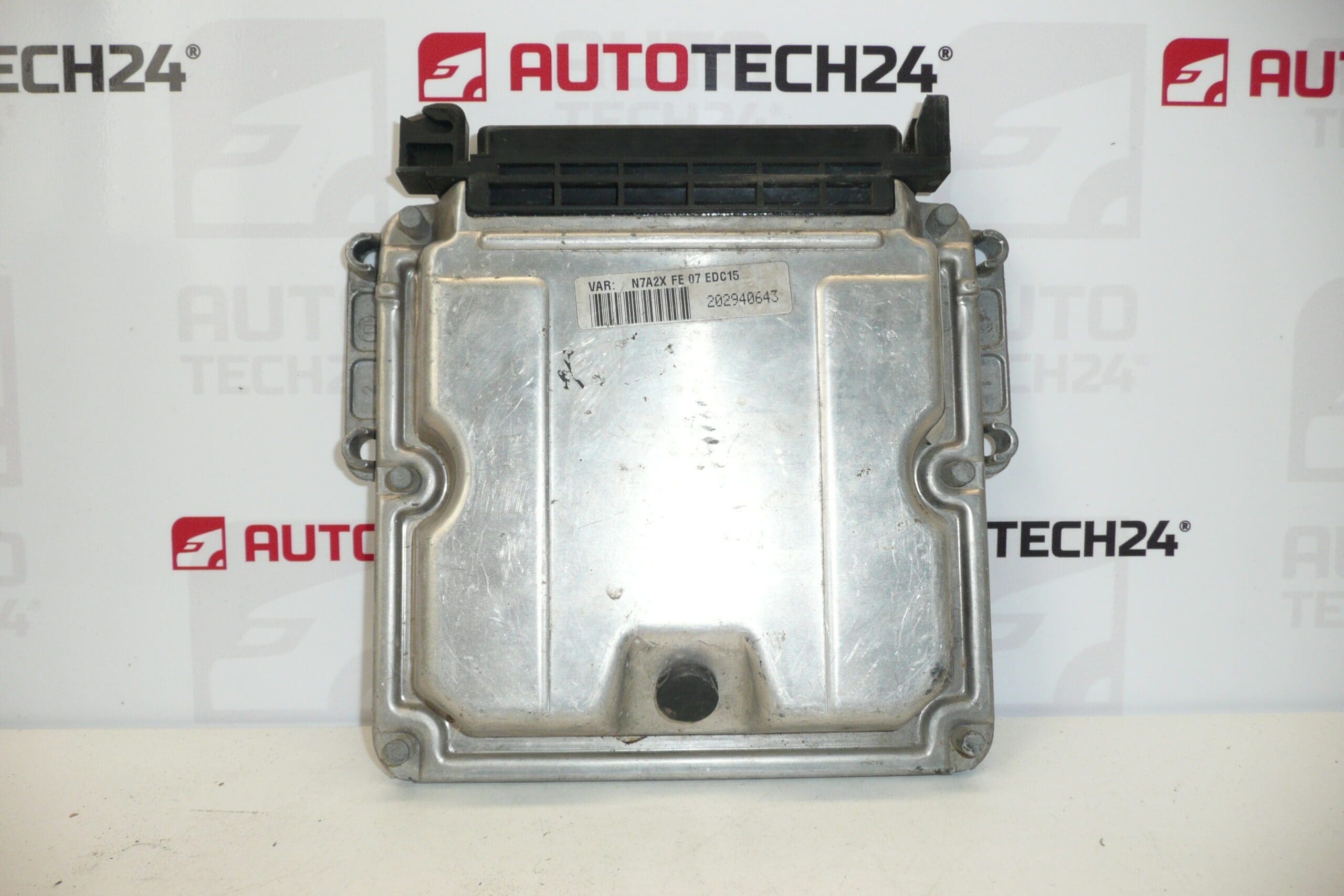
BOSCH EDC15C2 control unit for CITROEN XSARA 2.0HDI cars
Part description
This Bosch EDC15C2 injection control unit is a used genuine auto part designed for Citroën Xsara 2.0HDI cars. It is an important electronic component of the engine management, which ensures the correct cooperation of the injection and other connected systems. When looking for a suitable part, it is essential to orientate yourself by the product number, because this is what is often decisive when replacing it.
The Bosch EDC15C2 unit is sought after mainly when repairing defects of the original ECU, when replacing after electrical damage or as a spare part to restore the function of the vehicle. For auto mechanics and home repairers, the possibility to compare the markings directly on the original piece and choose the appropriate part without unnecessary compromises is an advantage.
Technical information
- Manufacturer: Bosch
- Model: EDC15C2
- Other numbers: 0281010550, 9641608480
Product codes
Product codes: 0281010550, 9641608480
Model names: CITROEN XSARA
Installation recommendations
This part is an injection control unit. The exact replacement procedure may vary according to the specific design of the car, therefore the procedure below is based on the general practice typical for this type of electronic part.
1) Before assembly
- Check that the manufacturer, unit type and all product numbers match the old part.
- Compare the connectors, their number, shape and pin condition.
- Inspect the unit case for cracks, deformation or moisture damage.
- Check both old and new units for signs of significant overheating or contact oxidation.
2) Necessary tools and materials
- Basic set of hand tools
- Suitable bits or sockets for removing the bracket and covers
- Cleaning agent for electrical contacts
- Antistatic and clean work surface
- Diagnostic equipment suitable for subsequent adjustment and function check
3) Step-by-step assembly procedure
- Park the vehicle in a safe place, turn off the ignition and wait for the electrical systems to calm down.
- Disconnect the battery to avoid damaging the electronics during handling.
- Access the control unit by removing the covers or brackets, if they are present in the given version of the car.
- Carefully disconnect the electrical connectors. Do not use excessive force and check the locking mechanisms.
- Remove the original unit from the holder and match it with the replacement unit by label, numbers and connectors.
- If necessary, gently clean the connectors and the surrounding area of the installation site from dust and oxidation.
- Place the replacement unit in the holder in the same position as the original part.
- Connect the connectors so that they fit properly and are secured by locking.
- Reinstall all brackets, covers and fasteners.
- Connect the battery and perform a basic power and communication check of the unit.
- If necessary for the system, have the drive professionally encoded or initialized.
- Once completed, verify that the vehicle responds correctly when the ignition is turned on and that there are no obvious electrical errors.
-
4) Post-assembly checks and test drive/function verification
- Check that all connectors are firmly seated and there is no tension.
- Verify the basic operation of the system after turning on the ignition and after starting.
- Perform a diagnostic check if appropriate equipment is available.
- During the test drive, observe the smoothness of the engine, the reaction to the gas and any warning lights.
- After driving, visually check again the fastening of the unit and the condition of the connectors.
5) The most common assembly mistakes + how to avoid them
- Swap by look-alike instead of number – always match the exact unit designation.
- Connecting with battery connected – always disconnect vehicle power first.
- Damage to the pins in the connector – disconnect and connect the connectors only in the correct direction and without force.
- Underestimation of contact oxidation – check the cleanliness and condition of electrical connections before assembly.
- Omission of coding or initialization – with used control units, it is often necessary to expect professional adaptation.
Assembly and Coding – Important
- The unit is used and is “paired” with the original car (VIN/PIN/keys).
- Commissioning options:
- Cloning data from the old drive (EEPROM/Flash) – after the clone, the drive is plug and play.
- Virginization and subsequent initialization/telecoding via DiagBox (possibly online) + customization of keys.
- Recommended to be performed by an expert with PSA service equipment (DiagBox/Lexia/PP2000).
- Always disconnect the battery before disassembly/assembly and follow the manufacturer’s procedure to avoid damaging the unit.
Reasons why the part is damaged
- Voltage fluctuations in the electrical system or problems with the vehicle’s power supply
- Moisture and oxidation which can damage electronics and connectors
- Overheating caused by inappropriate operating conditions or malfunction in surrounding systems
- Mechanical damage due to improper disassembly, assembly or impact
- Damage to connectors and pins due to careless handling
- Short circuit or other electrical fault in the vehicle installation