Description
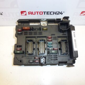
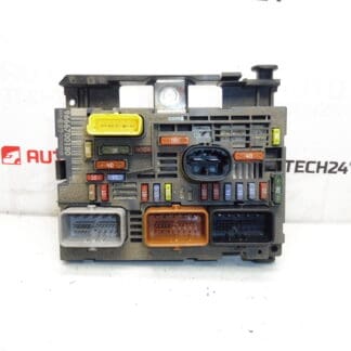
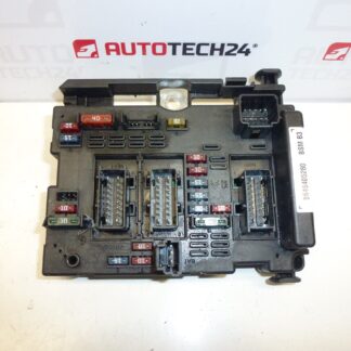
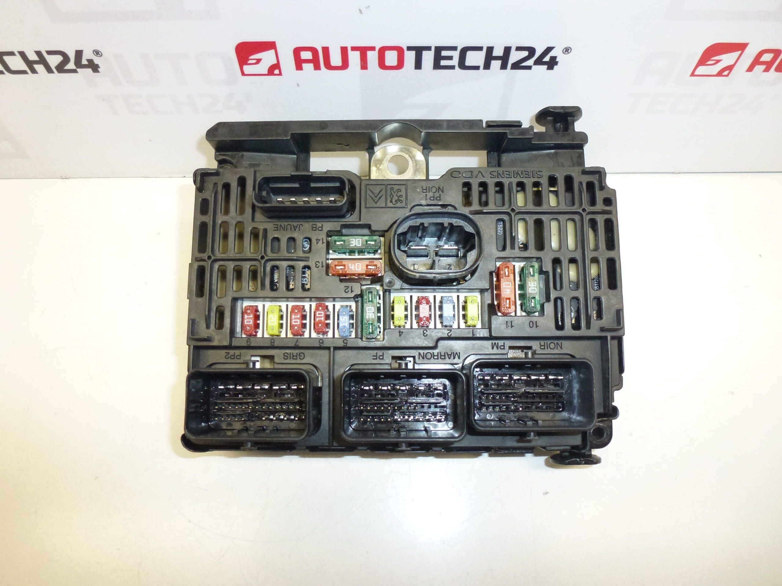
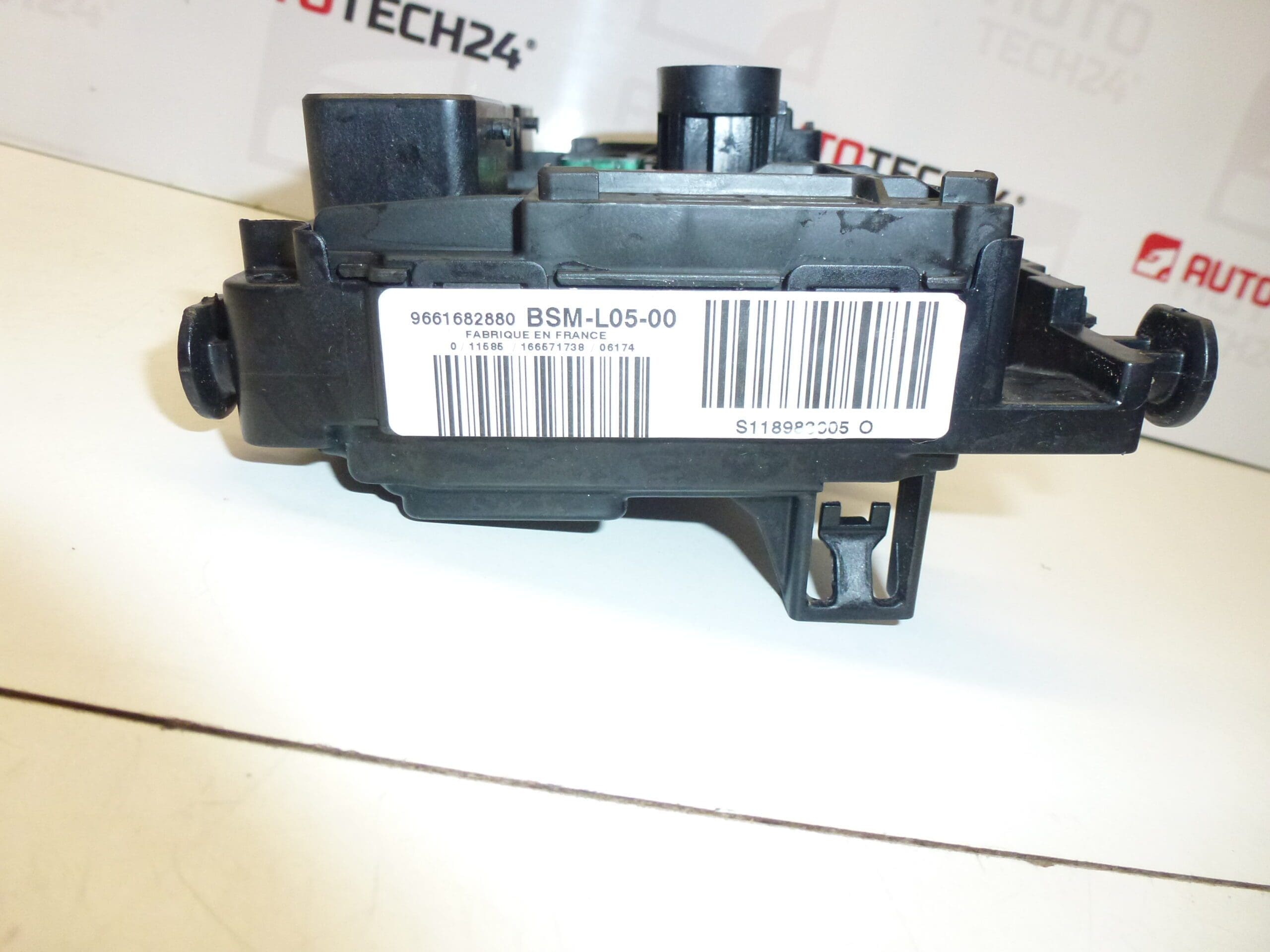
BSM L05-00 Siemens VDO for Citroën and Peugeot vehicles. Fits Citroën C8 II, Jumpy II, Peugeot 807, Expert, Fiat Scudo 2007. The unit is fully functional with no faults. It may have a cracked mounting clip on the housing, which does not affect function.
This BSM L05-00 control unit from Siemens VDO is a direct-fit electronic control module used on a range of Stellantis passenger and light commercial vehicles. Designed for professional workshops and experienced DIY technicians, the unit manages engine-related signals and electrical interfaces required for reliable vehicle operation. Supplied as a ready-to-fit module, it represents a practical replacement when the original BSM shows faults or communication errors.
Technical Information
- Manufacturer: Siemens VDO
- Model: BSM L05-00
- Product Codes: BSM L05-00, S118983005Q, S118983005O
- Additional Numbers: 9661682880, 6500CK
- Compatible Vehicles (examples): Citroën C8 II, Citroën Jumpy II, Peugeot 807, Peugeot Expert II, Fiat Scudo (2007)
Typical function: The module controls and monitors engine-related inputs and outputs, processes sensor signals and drives actuators as part of the vehicle management system. It communicates with other control units on the vehicle bus and is essential for correct engine running and diagnostics.
Installation Recommendations
- Disconnect the negative battery terminal before starting work to prevent short circuits and unintended faults.
- Locate the BSM unit according to vehicle model (refer to factory repair manual); common positions are under the dashboard or in an engine bay housing depending on the model.
- Carefully release all connector locks and document connector positions. Avoid pulling on wiring—use the connector body.
- Replace any broken mounting clips to secure the unit; cosmetic damage to clips does not affect electrical function but secure mounting prevents vibration issues.
- After mechanical installation, perform an electrical check and clear any stored fault codes. In many cases a diagnostic tool is required to verify communication and to complete any necessary coding or parameter adaptation.
- Test drive the vehicle and monitor for fault codes or abnormal behaviour. Re-check connector seating and grounding if intermittent faults persist.
Why This Part Fails Most Often
- Water ingress or moisture leading to corrosion of PCB traces or connector pins.
- Heat cycling and thermal stress that degrade solder joints or electronic components over time.
- Electrical surges, poor grounding or short circuits that damage internal electronics.
- Mechanical damage to connectors and mounting points caused by vibration or improper handling.
- Software or communication faults arising from bus errors or failing partner modules.
For professional installation and reliable results, use a compatible diagnostic tool to confirm unit communication and to perform any required coding or immobilizer/ECU adaptations after replacement.