Description
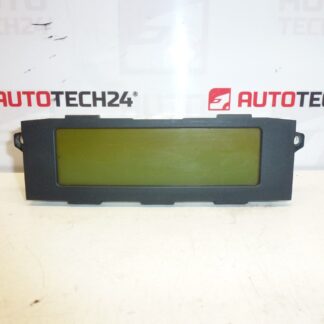
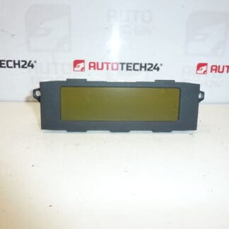
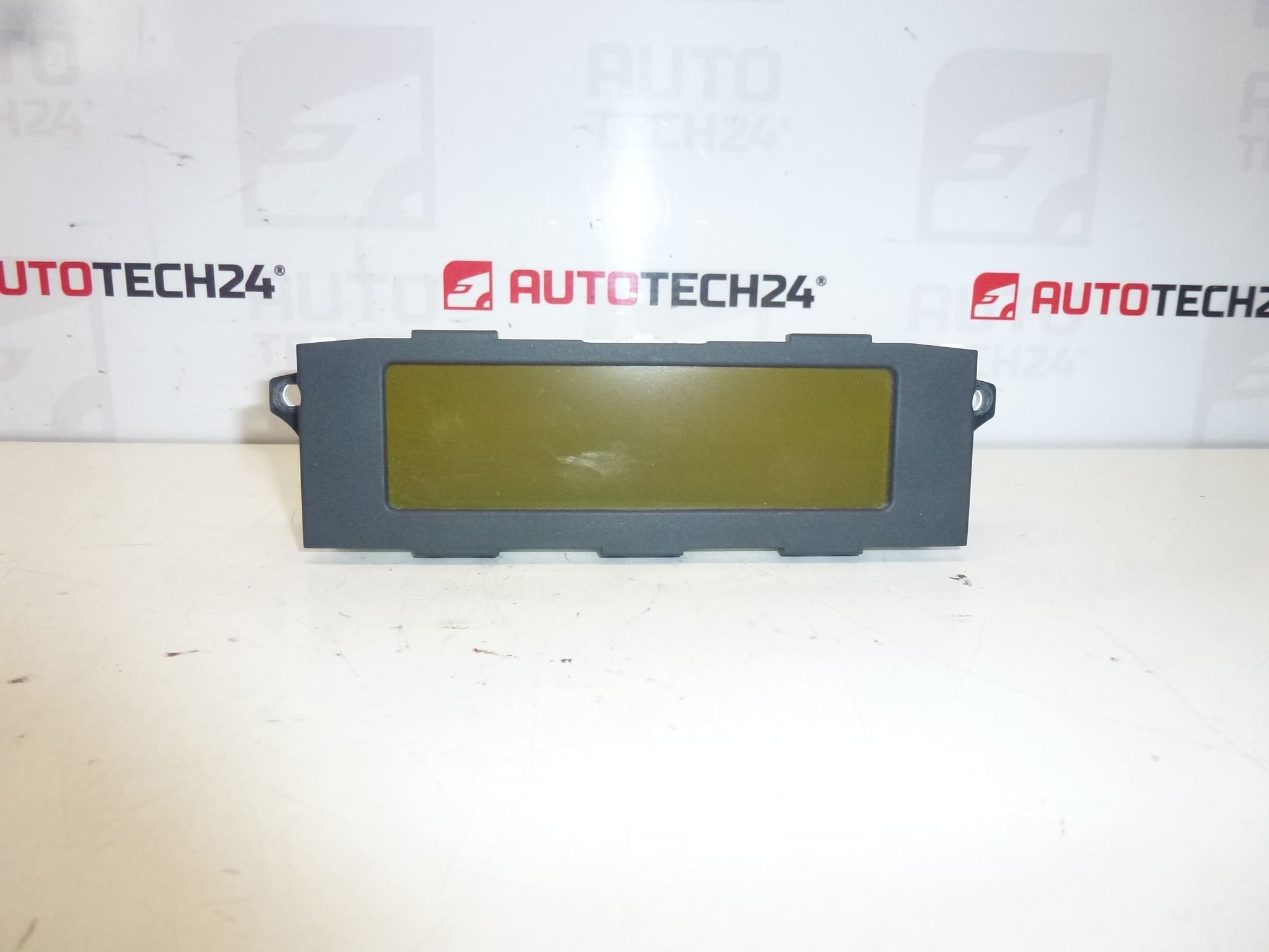
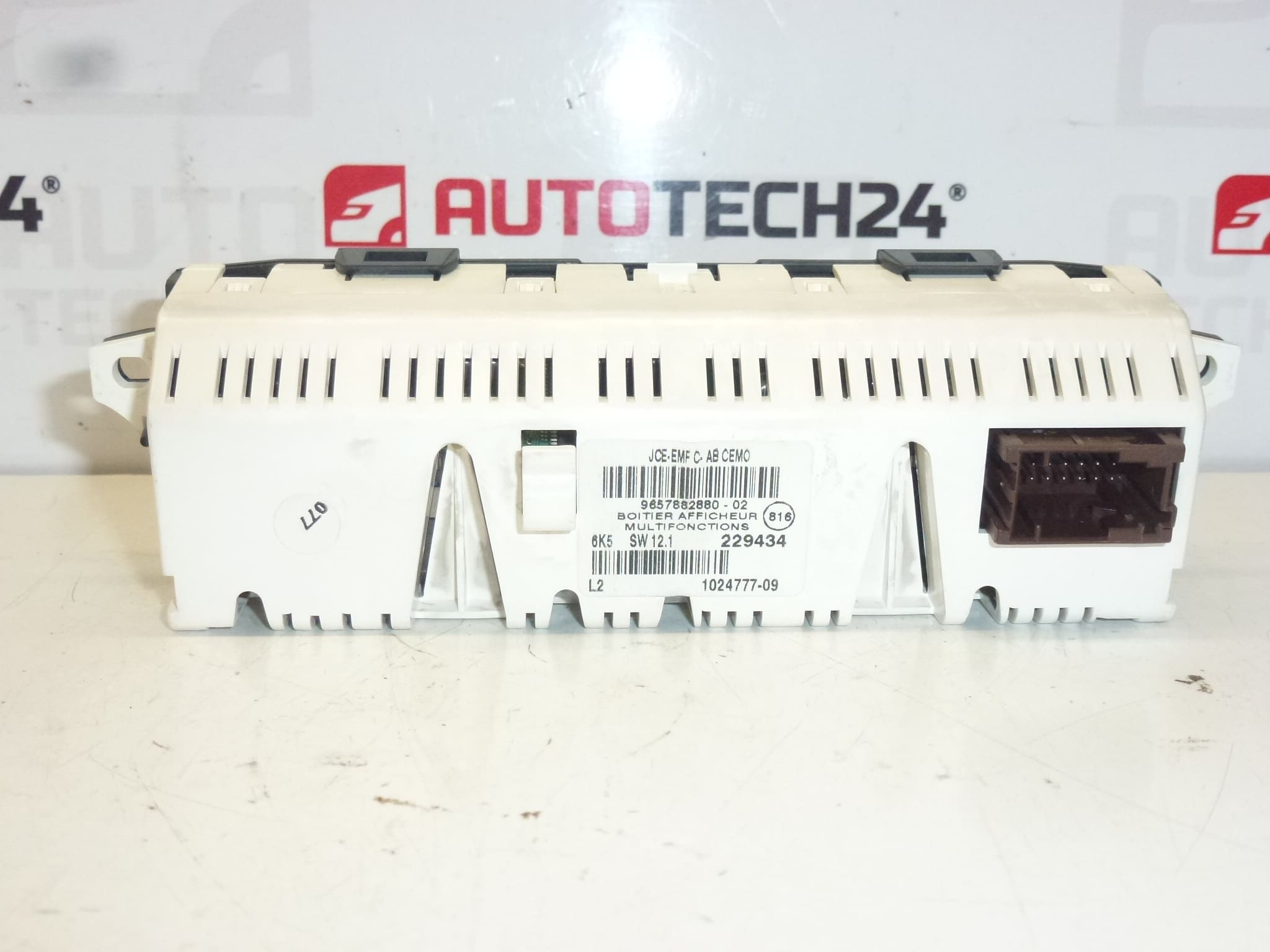
Display for radio and trip computer Citroën C5 from 2005 to 2007
Product Overview
This replacement display is intended for the factory radio and onboard computer in Citroën C5 second‑generation vehicles produced in the mid‑2000s. It restores clear readout of radio stations, clock, trip computer data and status messages. The unit is a direct replacement for the OEM display fitted in many C5 models and is commonly searched by part numbers 9657882880, 9657882880-02 or 6593T2.
Why Choose This Display
Ideal for professional workshops and competent DIY mechanics who need a reliable, vehicle‑specific display. Installing a sound display improves driver information flow (radio, time, temperature, onboard computer readouts) and eliminates distracting blank or distorted screens. The product is particularly useful for vehicles with intermittent illumination, missing characters or failed backlight.
Technical Information
- Manufacturer: Stellantis / Citroén
- Model: Citroën C5 II (Second Generation), Model Years 2005–2007
- Product Codes: 9657882880, 9657882880-02
- Other Numbers: 6593T2
Typical Faults And Causes
Displays from this era most commonly fail due to age and environmental exposure. Typical causes include backlight burnout, failed or cracked solder joints on the display PCB, degraded electrolytic capacitors, thermal cycling stress and moisture or corrosion at connector pins. Symptoms are dim or blank screen, missing characters, vertical/horizontal lines and intermittent operation. Given the vehicle age, failures tend to increase after many years in service.
Replacement Procedure (Overview)
Recommended for experienced DIYers and professional technicians. Basic replacement steps:
- Disconnect the negative battery terminal before starting work to avoid short circuits and electronic damage.
- Remove surrounding trim panels using plastic trim tools to avoid scratches.
- Undo retaining screws securing the radio/display assembly and gently slide the unit out.
- Unplug all electrical connectors and any ribbon cables. Note connector orientation and locking tabs.
- Replace the faulty display with the new unit, reconnect connectors and reassemble in reverse order.
Installation Recommendations
- Always disconnect the battery before removal and follow manufacturer procedures to prevent damage to electronic modules.
- Use appropriate plastic trim tools and the correct screwdrivers/Torx bits to avoid panel damage.
- Inspect connector pins for corrosion and apply a light contact cleaner if necessary. Ensure firm, clean connections.
- After installation, verify power and ground at the unit and test radio, clock and trip computer functions before final reassembly.
Why The Part Fails Most Often
Long service life and exposure to heat and moisture are the main reasons for failure. Backlight LEDs or CCFLs age and dim, solder joints can crack from repeated temperature cycles, and capacitors on older boards may deteriorate. Poor connector contact or previous water ingress accelerates failure. Addressing underlying wiring or grounding issues reduces the risk of replacement soon after repair.
Notes For Professionals
Searchable by OEM numbers listed above — entering these product codes in parts catalogs or online search improves findability. Suitable for workshops performing on‑vehicle diagnostics and repairs; always verify functionality after installation and check related fuses and power feeds when troubleshooting display faults.