Description
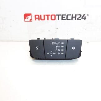
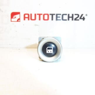
Hazard warning light switch for CITROEN, PEUGEOT and other Stellantis models
Part description
Used Citroën Peugeot hazard warning light switch with part numbers 9817043077 and 98170430ZD is used to switch the hazard warning lights on and off. It is a suitable choice when replacing a damaged or non-functional control button, provided it matches the original part in your vehicle.
When selecting a part, compare the product number, the shape of the switch, the mounting points and the connector design in particular. The same model name alone does not necessarily mean that the part has the same design. Replacing the switch itself may be a suitable solution if the fault is actually in its mechanism or electrical contacts, rather than in the wiring or other parts of the electrical system.
Technical information
- Manufacturer: not specified; the supplied materials identify Stellantis CITROEN PEUGEOT.
- Model: Citroën Berlingo K9; FIAT DOBLO III; OPEL COMBO E K9; PEUGEOT RIFTER; Toyota ProAce City.
- Part type: hazard warning light switch.
- Condition: used automotive part.
- Category: Electrical components / Other / Other controls and switches.
- Other numbers: not specified.
The models are taken from the supplied labels. Exact model years, engine types and equipment variants are not specified in the supplied materials.
Product codes
- Product codes: 9817043077, 98170430ZD.
Both numbers are listed in the materials for this switch. Before purchasing, compare them with the number on the original part and also check its mechanical and electrical design.
Installation recommendations
The following procedure generally applies to this type of electrical switch. The exact method for accessing, releasing and connecting it depends on the specific vehicle model and design. Follow the manufacturer’s service procedure and do not force the part out.
1) Before installation
- Verify that the switch is the cause of the fault. Non-functional hazard warning lights may also be related to the power supply, connector or wiring.
- Compare the part numbers, dimensions and housing shape, mounting points, connector and contact layout with the old part.
- Inspect the used switch: check for cracks, damaged clips, signs of moisture, corrosion and deformed contacts.
- Gently test the button’s movement. It should not stick mechanically; however, smooth movement alone does not confirm that it works electrically.
2) Tools and materials required
- Plastic tools for careful trim removal.
- Standard hand tools suitable for the vehicle’s actual fasteners.
- A flashlight, a clean cloth and protection for surrounding visible surfaces.
- If needed, a multimeter and an electrical contact cleaner suitable for the surrounding materials.
3) Step-by-step installation procedure
- Park the vehicle in a safe place, secure it against movement, and switch off the ignition and electrical accessories.
- Follow the service instructions to allow the electrical systems to enter their standby state, then disconnect the battery as specified.
- Protect the surrounding surfaces and access the switch according to the procedure for the vehicle in question. Before prying, check whether other fasteners are holding the trim in place.
- Record the original position of the switch and the routing of the wiring, for example by taking a photograph.
- Carefully release the switch’s fasteners and pull it out only far enough to avoid straining the connected wires.
- Release the connector lock and disconnect it by pulling on its housing, not the wires.
- Inspect the connector and accessible wiring. Loose, corroded or heat-damaged contacts should first be professionally repaired.
- Compare the two switches once more. If the connector or mounting differs, do not proceed by forcing them to fit.
- Connect the replacement switch and make sure the connector is properly secured. Route the wiring so that it is neither stretched nor pinched.
- Fit the switch into its original mounting and reinstall the removed trim. Check that it is firmly seated and that the button moves freely.
- Reconnect the battery according to the manufacturer’s instructions and check the switch’s operation.
4) Post-installation checks and function test
- With the vehicle stationary, switch the hazard warning lights on and off and check that they work on all relevant direction indicator lights.
- Check the dashboard indicators and the normal operation of the direction indicators.
- Test the button repeatedly and check that it responds reliably and does not rub against the surrounding trim.
- A stationary check is generally sufficient to verify the switch itself. If the lights do not work properly, resolve the fault before driving.
5) Common installation mistakes and how to avoid them
- Selecting by appearance alone: also compare the part number, connector and mounting.
- Breaking the clips: first determine how the part is secured and use reasonable force.
- Pulling on the wires: always release the connector lock first and grip the connector housing.
- Pinching the wiring: check its routing before fully seating the part.
- Replacing the part without identifying the cause of the fault: a damaged connector or broken wire will not be fixed by a new switch.
Reasons why the part can become damaged
Faults in this type of switch may generally occur for the following reasons; this is not a description of the condition of the item being offered:
- Mechanical wear of the button and internal switching mechanism after prolonged use.
- Ingress of liquid, moisture or dirt, which may cause contact corrosion or make the button stick.
- Excessive pressure or impact, which may crack the switch housing or its mounting.
- Careless removal, especially prying without releasing the clips and pulling on the wiring.
- Poor electrical contact in the connector, which may cause intermittent operation or localized overheating.