Description
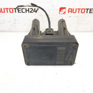
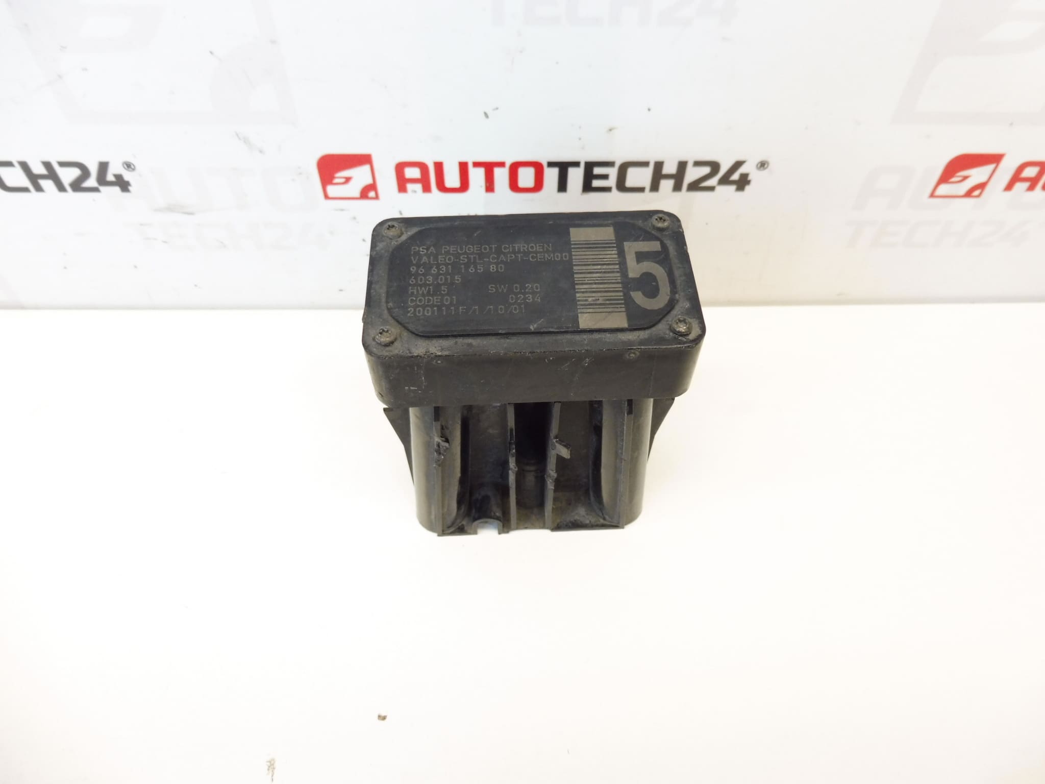
AFIL lane-keeping sensor number 4 for Citroën and Peugeot vehicles. A screw that secures the unit to the wheel arch may be seized — drilling out is necessary.
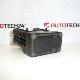
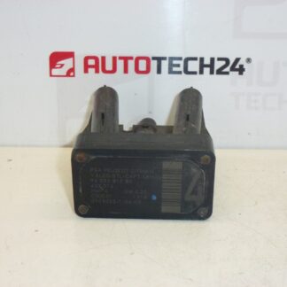
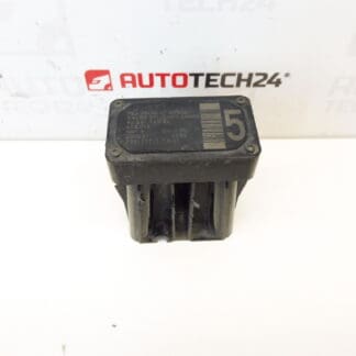
This AFIL (Lane Departure Warning) sensor is an original-equipment-style replacement designed for Citroën and Peugeot vehicles that use the Stellantis ADAS system. It provides the electronic input for lane monitoring functions, allowing the vehicle to detect lane markings and warn the driver or assist lane-keeping features where fitted. The part is often searched and ordered by its product numbers 9663116580 and 6590W1, so listing those codes in your search will speed up finding the correct unit.
Technical Information
Manufacturer: Citroën / Peugeot (Stellantis)
Model: Citroën C4; Citroën C4 Picasso; Citroën C5; Citroën C5 X7; Citroën C6; Peugeot 308; Peugeot 407
Product Codes: 9663116580, 6590W1
Additional Numbers: AFIL Sensor
Function And Benefits
The AFIL sensor monitors lane markings and provides data to the vehicle’s lane departure warning/assistance system. Correct operation improves active safety by reducing unintentional lane departures and providing early alerts to the driver. For workshops and DIYers, replacing a faulty sensor restores ADAS functions and removes related dashboard warnings or fault codes.
Installation Recommendations
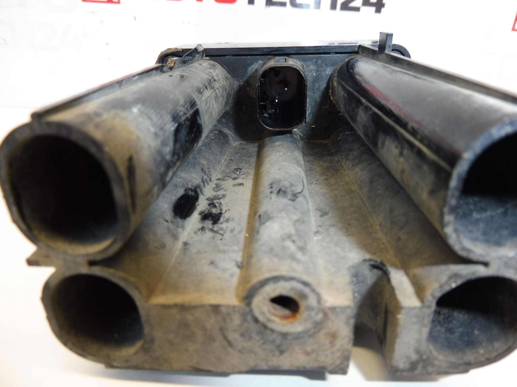
Access The Unit Through The Wheel Arch Or Inner Trim: Remove The Wheel Arch Liner Or Interior Trim Panels To Reach The Sensor. Disconnect The Electrical Connector Before Removing Mounting Hardware. Be Prepared For A Seized Or Corroded Screw: As Noted, The Fastening Screw That Secures The Unit To The Wheel Arch Can Be Seized And May Need To Be Drilled Out Carefully. Use Appropriate Tools And Eye Protection.
Inspect Wiring And Connectors For Corrosion Or Damage And Replace Any Compromised Clips Or Seals. Replace Corroded Fixings With New Hardware And Apply Anti-Seize Or Appropriate Threadlocker If Specified By Manufacturer. Tighten Fasteners To Manufacturer Torque Values Where Available.
After Mechanical Replacement: Clear Stored Fault Codes And Verify System Operation. Many ADAS Sensors Require Calibration Or Adaptation Via Diagnostic Equipment Or A Short On-Road Calibration Procedure; Follow The Vehicle Manufacturer’s Service Instructions For Final Setup.
Why This Part Commonly Fails
Common Causes Of Failure Include Water Ingress And Corrosion, Physical Damage From Impacts Or Road Debris, Electrical Connector Corrosion, Or Internal Electronics Degradation. Mounting Hardware Often Seizes Due To Corrosion, Which Is The Reason A Screw May Need To Be Drilled Out During Replacement. Faults Typically Present As Warning Lights, Stored ADAS Fault Codes, Or Loss Of Lane Monitoring Function.
Suitable For Professional Workshops And Experienced DIY Mechanics. If You Frequently Search By Part Number, Use 9663116580 Or 6590W1 To Find This Exact Sensor Quickly.