Description
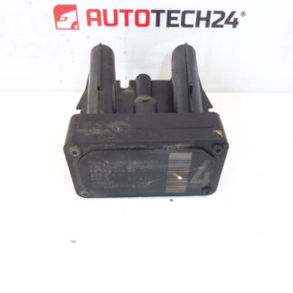
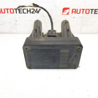
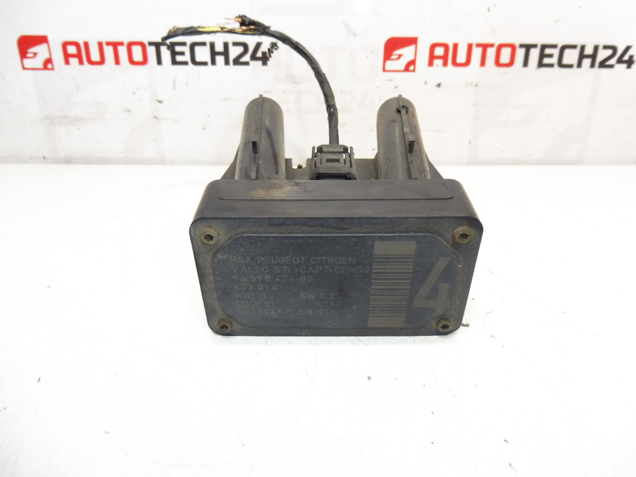
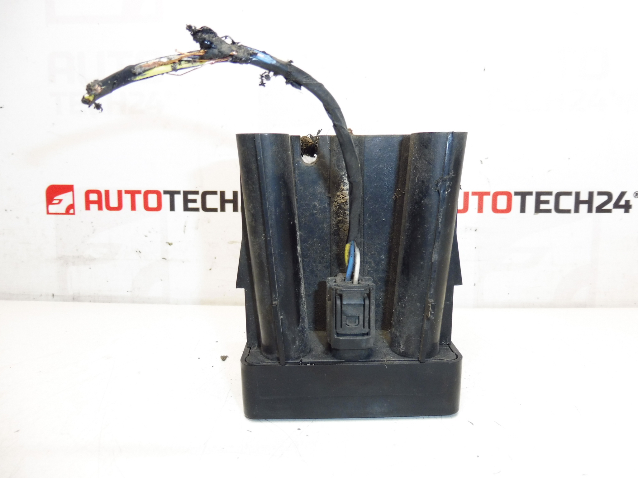
AFIL lane-keeping sensor number 4 for Citroën and Peugeot vehicles. A seized screw that holds the unit to the wheel arch may need to be drilled out.
This AFIL (Lane Departure/Lane-Keeping) sensor is a direct-fit component for a range of Citroën and Peugeot models and is commonly referenced by OE numbers when searching or ordering. Designed for professional workshops and competent DIY mechanics, the unit detects lane markings and supplies vital input to the vehicle’s driver assistance system. Replacement of this sensor restores correct lane-monitoring functionality and eliminates warning messages or degraded assistance performance.
Technical Information
- Manufacturer: Stellantis (Citroën / Peugeot)
- Model: Citroën C4, Citroën C4 Picasso, Citroën C5, Citroën C5 X7, Citroën C6, Peugeot 308, Peugeot 407
- Product Codes: 9659847480, 603.014, 6590W1
- Other Numbers: Commonly Cross-Referenced Under The Above OE Codes
Installation Recommendations
- Disconnect The Battery Before Starting Work To Avoid Short Circuits And Airbag/ECU Faults.
- Raise The Vehicle Safely And Remove The Wheel If Needed To Access The Wheel Arch Liner.
- Remove The Wheel Arch Liner To Expose The Sensor Housing. The Unit Is Usually Secured To The Arch With Screws Or Clips.
- If A Mounting Screw Is Seized, Drill Or Carefully Extract It As Noted In The Original Service Tip. Use Proper Extraction Tools To Avoid Damaging The Housing.
- Unplug The Electrical Connector By Releasing Any Locking Tabs; Inspect For Corrosion Or Damaged Pins.
- Fit The Replacement Sensor, Use New Fasteners Or Clips If Original Fixings Are Damaged, Reinstall The Liner And Wheel.
- Reconnect The Battery And Clear Fault Codes With A Diagnostic Tool. The AFIL/Lane System May Require A System Check Or Calibration With A Suitable Diagnostic Tool Or Workshop Equipment.
- Replace Any Damaged Seals Or Grommets To Prevent Future Water Ingress.
Why The Part Commonly Fails
- Water Ingress And Corrosion Of Connectors Or Internal Electronics, Especially In Areas With Salted Roads.
- Mechanical Damage From Road Debris Or Bumper/Wheel Arch Impacts.
- Wiring Harness Damage Or Poor Electrical Contact At Connectors.
- Mounting Hardware Seizing Due To Corrosion—Which Can Make Removal Difficult And Lead To Additional Damage If Not Handled Correctly.
- Environmental Ageing: Rubber Grommets, Seals And Internal Components Can Deteriorate Over Years Of Use.
Search By OE Number For Fast Identification: Customers And Workshops Often Locate This Sensor Using The Product Codes 9659847480, 603.014 Or 6590W1. If The Mounting Screw Is Seized, Prepare Appropriate Tooling (Screw Extractor, Drill Bits) And Plan For Possible Replacement Clips Or Fasteners During The Repair.
Typical Lifespan Depends On Usage And Environment; Regular Visual Inspection Of Mountings And Connectors Helps Prevent Sudden Failures. This Part Is Intended For Professional Fitting Or For Experienced DIY Mechanics Comfortable With Electrical Connectors And Accessing Wheel Arch Components.