Description
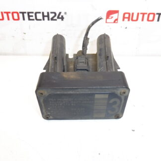
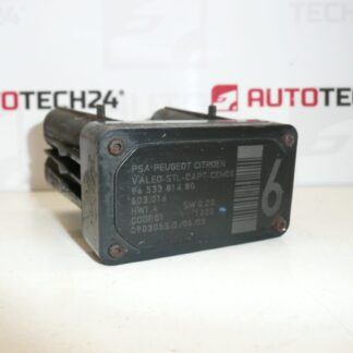
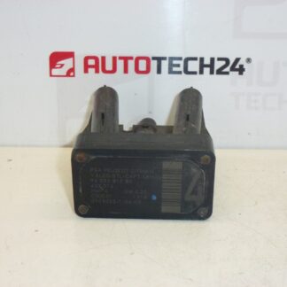
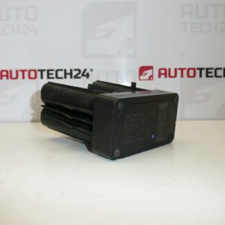
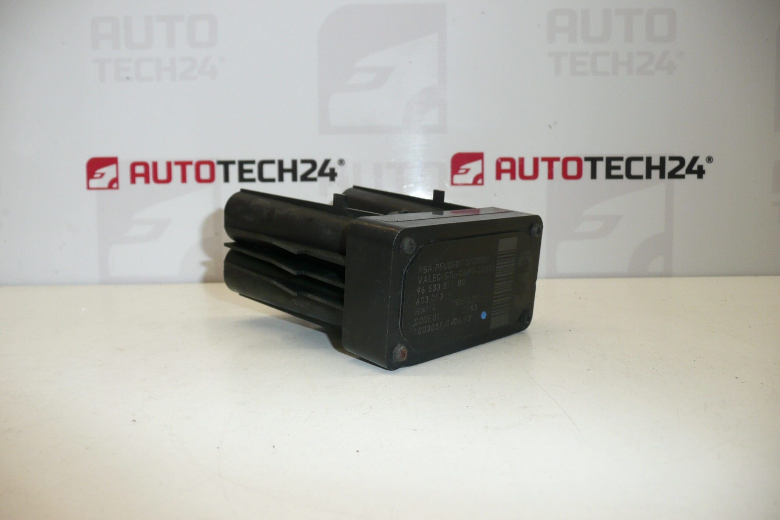
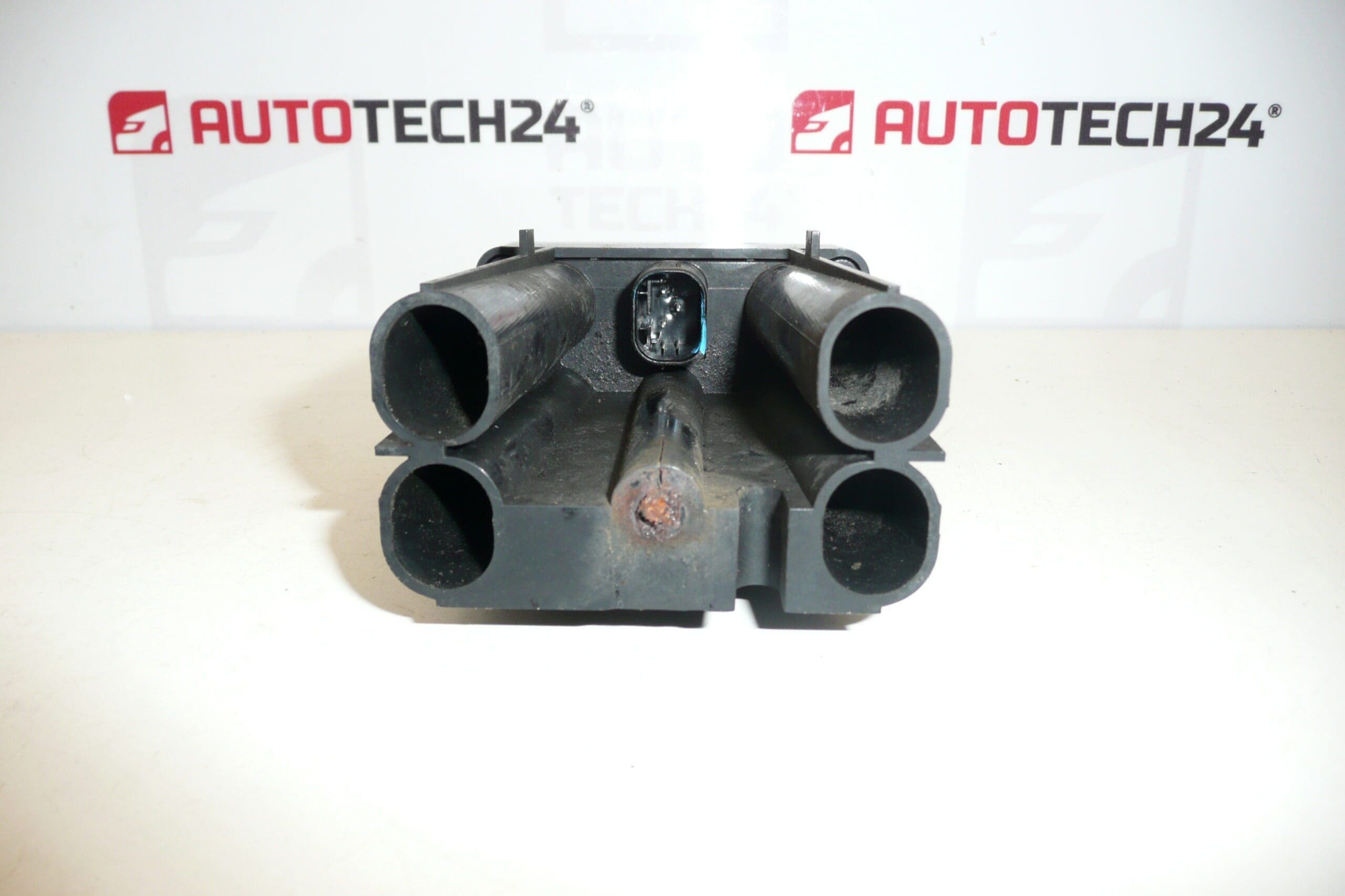
Lane monitoring sensor AFIL number 3 for Citroën and Peugeot vehicles. The screw that secures the unit to the wheel arch may be seized and needs to be drilled out.
This AFIL (lane monitoring) sensor is an original-equipment type unit used on a range of Citroën and Peugeot models to support lane departure detection and driver assistance systems. Designed for professional workshops and experienced DIY mechanics, the sensor replaces a faulty lane-monitoring module and restores correct operation of lane-keeping warnings. Common searchable references and OE numbers are included below to help you find the correct part quickly.
Technical Information
- Manufacturer: Stellantis / Citroën / Peugeot
- Model: Citroën C4, Citroën C4 Picasso, Citroën C5, Citroën C5 X7, Citroën C6, Peugeot 308, Peugeot 407
- Product Codes: 9653381180, 6590W1
- Other Numbers: 603.013
What The Part Does
The AFIL sensor monitors lane position and road markings to support lane departure warning and related driver assistance functions. It communicates with the vehicle’s safety and assistance control units to trigger visual or audible alerts when unintentional lane departure is detected. Proper operation is essential for systems that assist the driver in maintaining lane position.
How To Replace
Replacement is straightforward for a trained mechanic but can require basic workshop tools and access under the wheel arch. Typical replacement steps:
- Disconnect the negative battery terminal to prevent electrical faults.
- Raise the vehicle and remove the relevant wheel if needed for better access.
- Remove the wheel arch liner to expose the AFIL unit and mounting point.
- Disconnect the sensor electrical connector and remove the mounting fasteners. If the mounting screw is seized, drill or carefully extract the screw as noted above.
- Fit the new sensor using new corrosion-resistant fasteners, reconnect the electrical connector and reassemble the wheel arch liner and wheel.
- Reconnect the battery, perform a basic system check and, where applicable, carry out electronic calibration using a diagnostic tool to ensure correct lane-detection alignment.
Installation Recommendations
- Always Use Replacement Fasteners: Replace seized or corroded screws with new stainless or coated fasteners to avoid future seizure.
- Protect Connectors: Clean and apply dielectric grease to connectors to prevent corrosion and poor contact.
- Require Calibration: After replacement, perform a diagnostic check and calibration where the vehicle manufacturer specifies it to ensure system accuracy.
- Workshop Tools: Have an impact driver, extraction drill set for seized screws and a diagnostic scanner capable of AFIL/ADAS checks available.
Why This Part Fails Most Often
- Seized Mounting Screw: Corrosion from moisture and road salt commonly seizes the screw that secures the unit to the wheel arch, making removal difficult.
- Water Ingress And Corrosion: Prolonged exposure to moisture and salt can corrode electronics and connectors, causing intermittent or permanent failure.
- Mechanical Damage: Impacts, scrapes or collisions to the wheel arch area can misalign or damage the sensor housing.
- Connector And Wiring Faults: Damaged or corroded wiring and poor connector contact are frequent causes of sensor errors.
Part references included (9653381180, 6590W1, 603.013) are commonly used when searching for compatible AFIL sensors for Citroën and Peugeot vehicles. If you are replacing a sensor after seizure of the mounting screw, prepare appropriate extraction tools and replacement fasteners to ensure a durable repair.