Description
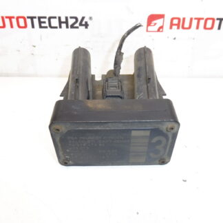
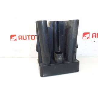
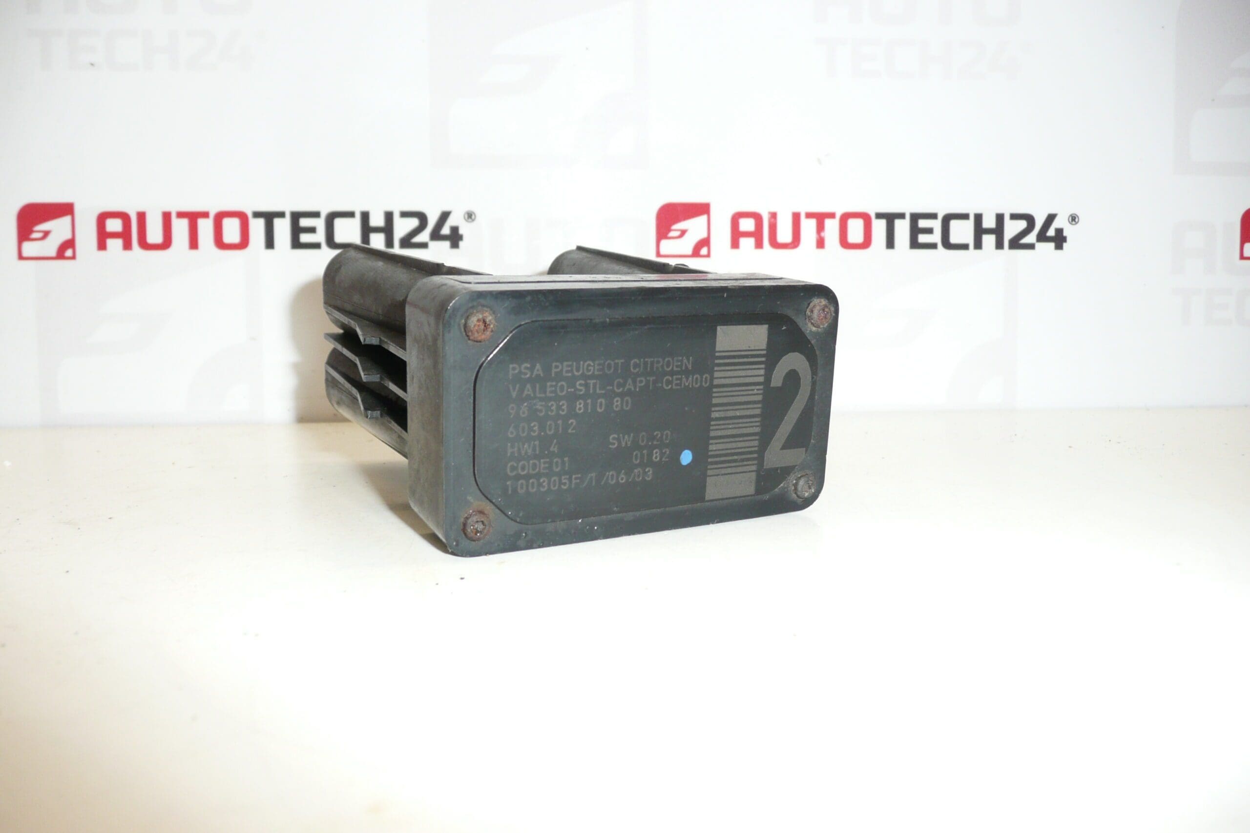
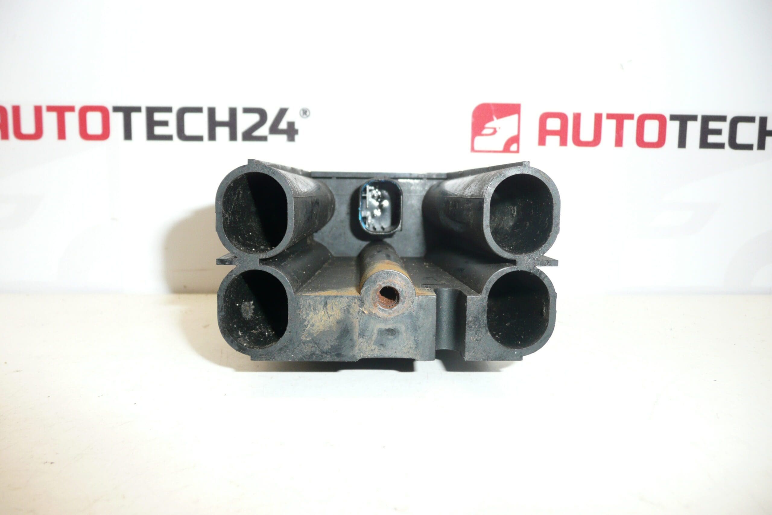
AFIL lane departure monitoring sensor number 2 for Citroën and Peugeot vehicles. A screw that secures the unit to the wheel arch may be seized — it may need to be drilled out.
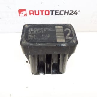
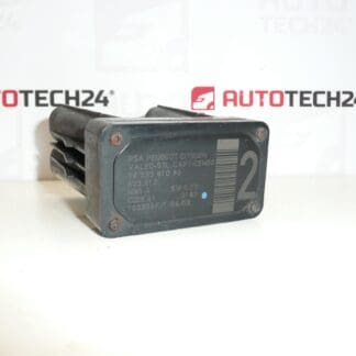
High-quality AFIL (lane departure) sensor compatible with a range of Citroën and Peugeot models. This sensor is often searched by part numbers 9653381080, 6590W1 or 603.012, so listing those codes here increases findability for professional mechanics and DIY enthusiasts. The unit monitors lateral vehicle position and provides input to lane departure warning / lane monitoring systems — a reliable replacement part for workshops and home repairs.
The AFIL sensor is a small but critical component of the vehicle’s driver assistance suite. It detects lane position and sends signals to the vehicle’s control unit to trigger warnings or corrective actions depending on the system. Faulty sensors can cause lane warning faults, erroneous alerts, or deactivation of the function. Because this part is commonly replaced by technicians, the product listing highlights the exact OEM codes to help you find the correct item quickly.
Technical Information
- Manufacturer: Stellantis (Citroën / Peugeot)
- Model: Citroën C4; Citroën C4 Picasso; Citroën C5; Citroën C5 X7; Citroën C6; Peugeot 308; Peugeot 407
- Product Codes: 9653381080, 6590W1
- Other Numbers: 603.012
Installation Recommendations
Replacement is recommended for trained technicians or experienced DIYers. Typical replacement steps:
- Disconnect the negative battery terminal before starting to avoid electrical shorts.
- Remove relevant interior trim or wheel-arch liner to access the sensor mounting point.
- If the mounting screw is seized, carefully drill out or extract the fastener; take care not to damage the sensor housing or surrounding bodywork.
- Disconnect the electrical connector and inspect pins for corrosion; replace or clean as needed.
- Fit the new sensor using correct fasteners and torque values per workshop manual.
- After installation, perform diagnostic checks and ADAS initialization if required: many lane monitoring systems need a calibration or electronic reset using a diagnostic tool.
Why This Part Fails Most Often
The most common reasons for AFIL sensor failure are moisture ingress and corrosion of the connector, mechanical damage from impacts or road debris, and seized or corroded mounting screws that compromise the unit’s fitment. Electrical issues in the wiring harness or poor grounding can also lead to intermittent faults or complete failure. In some cases the sensor itself degrades electrically over time due to exposure to vibration and temperature cycles.
If you notice lane warning faults, persistent error messages, or inconsistent system behavior after driving over rough roads or after minor impacts, inspect the sensor and its mounting. Replacing the sensor and ensuring proper mounting and calibration usually restores correct function.
Part numbers in the listing (9653381080, 6590W1, 603.012) are provided to help you match the correct replacement quickly. Suitable for professional garages and competent DIY mechanics who service Citroën and Peugeot vehicles.