Description
SAGEM control unit for Citroën Berlingo and Peugeot Partner vehicles
With 1.4 I KFW engine
Part description
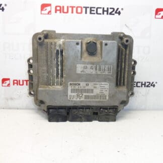
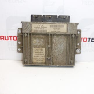
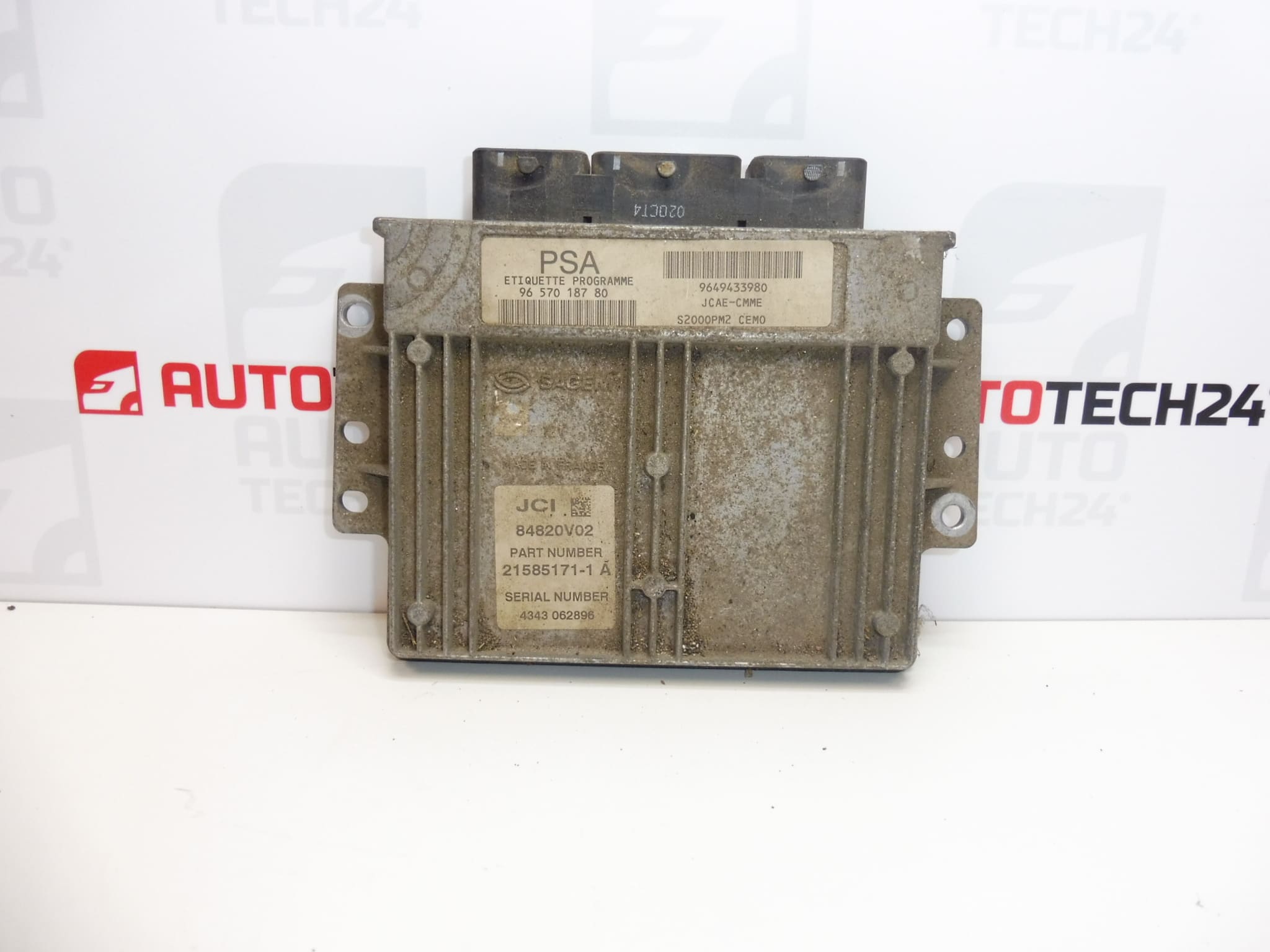
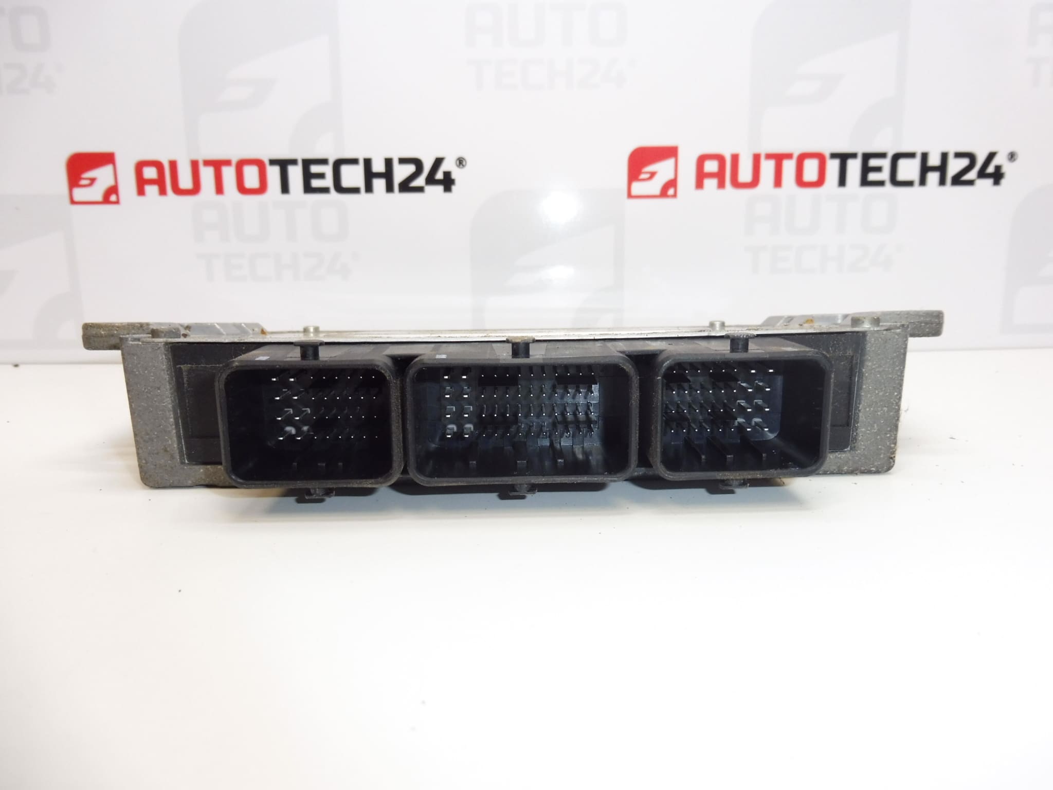
Used Sagem S2000PM2 fuel injection control unit for Citroën Berlingo and Peugeot Partner vehicles with 1.4 I KFW engine. The unit processes signals from sensors and controls the fuel injection system. When replacing faulty electronics, it is important to select the correct version and ensure that the data is transferred correctly or that the unit is adapted to the vehicle.
When searching for a replacement part, refer in particular to the markings 9657018780 and 9649433980 and the S2000PM2 type. A used part offers an alternative to purchasing a new unit; however, before installation, you must confirm the cause of the fault and prepare a method for putting the unit into operation.
Technical information
- Manufacturer: SAGEM
- Model: Citroën Berlingo, Peugeot Partner
- Unit type: S2000PM2
- Engine: 1.4 I KFW
- Part category: fuel injection control unit
- Condition: used part
- Additional numbers: 1940KJ, 194411
- Vehicle model years: not specified
Product codes
- Product codes: 9657018780, 9649433980, 1940KJ, 194411
- Type designation: Sagem S2000PM2
Compare the markings with the original unit and the service documentation for the specific vehicle. Matching the model name and engine alone may not be enough to identify the correct version of the electronics.
Installation recommendations
The following procedure is general guidance for replacing a fuel injection control unit. The exact removal, electrical checks and adaptation procedure depend on the specific model and vehicle version. We recommend having the replacement carried out by a specialist experienced with PSA electronics.
1) Before installation
- Use diagnostic equipment to confirm that the unit itself is actually the cause of the problem, rather than the power supply, ground connection, wiring or a connected component.
- Compare the product numbers, type designation, connectors and mounting points with the old unit. Assess hardware and software compatibility using the service documentation.
- Inspect the casing and connectors of the used part. Check for signs of moisture, corrosion, deformed contacts or mechanical damage.
- Determine in advance how the data will be transferred or the unit adapted. Keep the original unit in case its data needs to be read or backed up.
2) Tools and materials required
- Standard hand tools suitable for the fasteners used, and appropriate tools for carefully releasing the connectors.
- PSA diagnostic equipment and, depending on the method selected, equipment for working with the unit’s memory.
- A multimeter, service documentation and products suitable for cleaning electrical contacts.
- A suitable stabilized power supply for diagnostics and programming, as required by the service procedure.
3) Step-by-step installation procedure
- If the original unit communicates, read and save the diagnostic data and available configuration.
- Back up the necessary data or prepare a plan for adapting the replacement unit. Read the memory only with the appropriate equipment and procedure.
- Switch off the ignition, allow the electronics to enter sleep mode as instructed by the manufacturer, and disconnect the battery before removal.
- Access the unit according to the service procedure for the specific vehicle. Before disconnecting anything, note the wiring routing and connector positions.
- Release the connectors and disconnect them carefully. Do not pull on the wires or pry against the contacts.
- Release the mounting and remove the original unit without straining the surrounding wiring.
- Check the connectors, wiring harness, power supply and ground connection. Fix any faults that may have caused the original unit to fail before connecting the replacement.
- Have the data cloned or the unit prepared for subsequent initialization, depending on the method chosen to put it into operation.
- Position the replacement unit, secure it as instructed by the manufacturer and connect the connectors. Check that the latches are fully engaged and that the wiring is routed freely without tension.
- Reconnect the battery according to the manufacturer’s procedure. If the chosen method requires initialization, telecoding and key adaptation, complete these using diagnostic equipment while maintaining a stable power supply.
- Verify communication with the unit and check that the configuration is correct. Only after all required procedures have been completed successfully should you check engine starting and operation.
4) Post-installation checks and test drive / function verification
- Check engine starting, engine stability and response to the accelerator pedal.
- Run a diagnostic check and assess any faults. Simply clearing the fault memory without fixing the cause is not sufficient.
- Check that the unit is secure, the connectors are locked in place, and the wiring is protected from abrasion or moisture.
- If the engine runs properly and the vehicle is safe to operate, take a short test drive and then repeat the diagnostic check.
5) Common installation mistakes and how to avoid them
- Replacing the unit without checking the cause: first check the power supply, ground connection and connected circuits to prevent the fault from recurring.
- Selecting a unit based only on the vehicle model: also compare the part numbers, version and configuration requirements.
- Connecting without adaptation: the used unit may not allow the engine to start simply by plugging it in. Prepare a method for putting it into operation in advance.
- Working with the power on or interrupting programming: disconnect the battery during removal as instructed by the manufacturer; during programming, ensure the specified stable power supply is maintained.
- Damaging the connectors: release their locking mechanism first and never force them with excessive force.
Installation and coding – important
- The unit is used and is “paired” with the original vehicle (VIN/PIN/keys).
- Options for putting it into operation:
- Cloning data from the old unit (EEPROM/Flash) – after cloning, the unit is plug and play.
- Virginizing followed by initialization/telecoding via DiagBox (possibly online) + key adaptation.
- We recommend having this carried out by a professional with PSA service equipment (DiagBox/Lexia/PP2000).
- Always disconnect the battery before removal/installation and follow the manufacturer’s procedure to avoid damaging the unit.
Reasons why the part may be damaged
Several factors can generally contribute to damage to fuel injection control units. This is not a description of the condition found on this specific unit:
- Moisture and corrosion in the connectors or inside the unit.
- Overvoltage and improper handling of the power supply, for example during unprofessional work on the electrical system.
- Short circuits in the wiring or connected components, which can overload the unit’s output circuits.
- Long-term exposure to heat and vibration, which contribute to the aging of electronic components and connections.
- Unprofessional opening or programming, which can cause mechanical damage or corrupt stored data.