Description
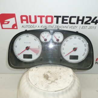
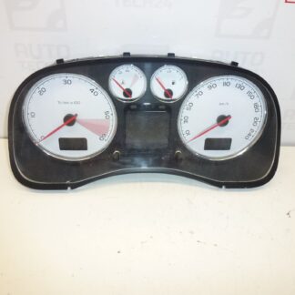
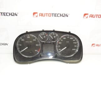
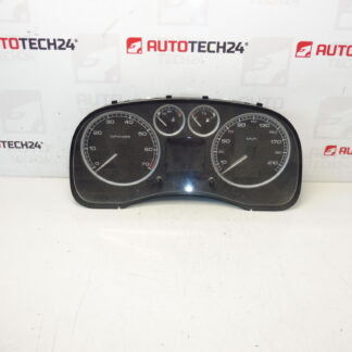
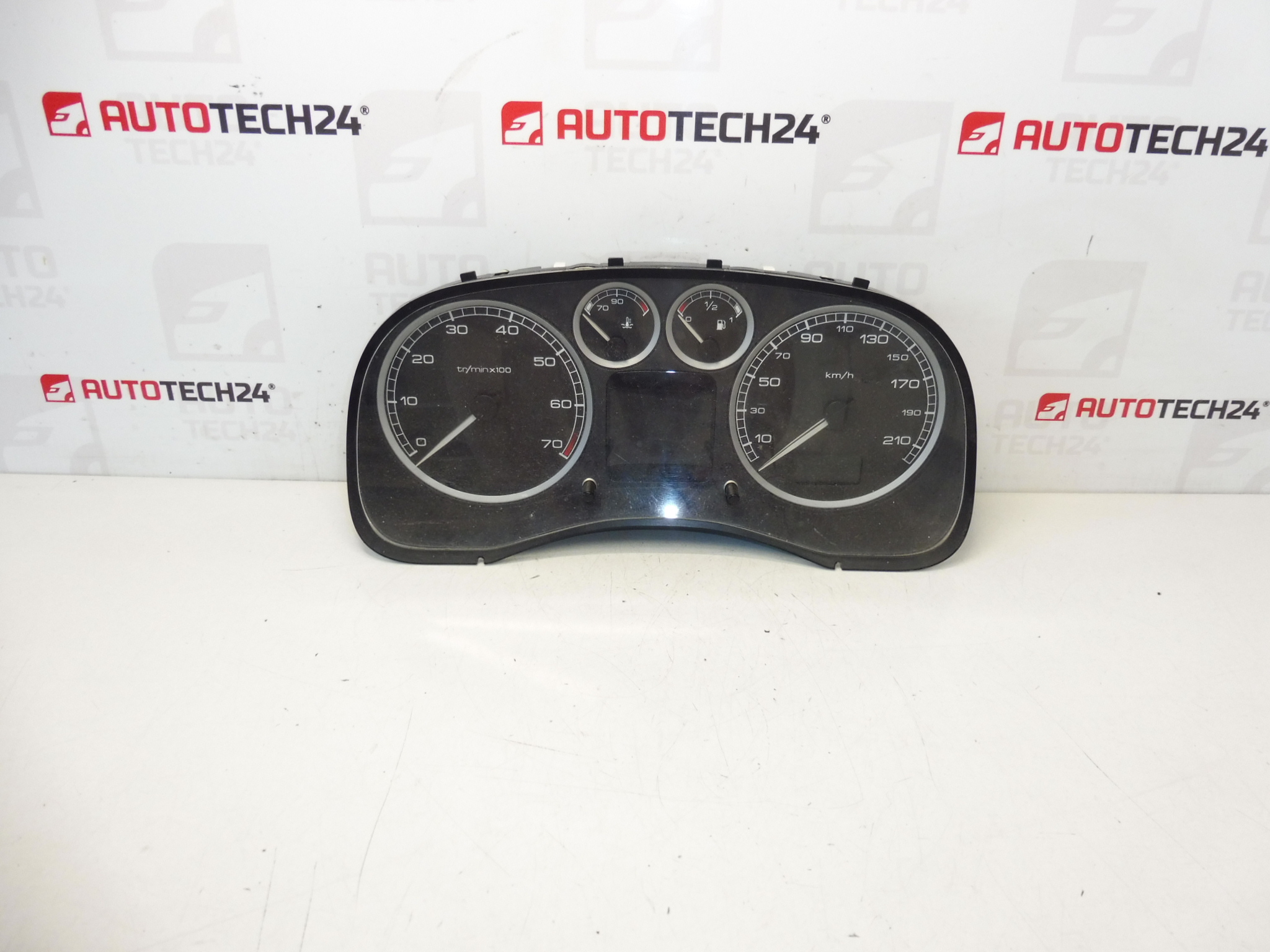
Speedometer for PEUGEOT 307 1.6 16V first series. Mileage unknown, approx. 200,000 km.
This is a used instrument cluster (speedometer) suitable for Peugeot 307 1.6 16V first-series cars. Ideal for professional mechanics and experienced DIYers searching by part number (P9645768480 / 9645768480 / 6103F7). The unit restores full instrument functionality — speedometer, odometer and dashboard indicator presentation — and is a practical replacement when the original cluster shows display or gauge faults. Compatible with vehicles that use the listed product codes; easy to fit for a workshop equipped for cluster swaps.
Function And Benefits
The instrument cluster provides the driver with essential information: vehicle speed, engine RPM (where applicable), odometer reading, warning lights and indicator lamps. Replacing a faulty cluster returns accurate dashboard readouts and restores visibility of warnings (ABS, airbag, engine management, etc.) that are crucial for safe diagnostics and operation. Sourcing a matching cluster by product code speeds up repair and reduces vehicle downtime.
Technical Information
- Manufacturer: Stellantis (Citroën / Peugeot)
- Model: Peugeot 307 (First Series), 1.6 16V
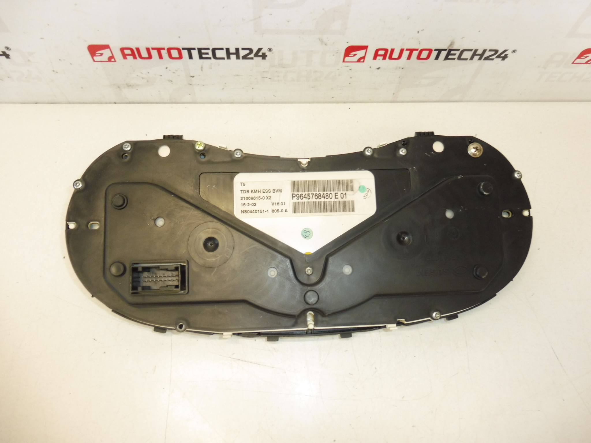
- Product Codes: P9645768480, 9645768480, 6103F7
- Other Numbers: 6106J6, 6106J7, E 01
- Mileage On Unit: Approximately 200,000 km (unknown exact value)
Replacement Procedure
Recommended steps for removal and installation (for experienced personnel):
- Disconnect the vehicle battery before starting to avoid short circuits and protect electronic modules.
- Remove trim panels and steering column covers to access the instrument cluster. Keep screws and fasteners organized.
- Unscrew the cluster fixing screws and carefully pull the unit forward to reach the electrical connectors.
- Release the locking tabs on the multi-pin connectors and unplug them. Inspect connectors for corrosion or bent pins.
- Swap the cluster, reconnect connectors firmly, refit the cluster and trim, then reconnect the battery.
- After installation, check all functions: backlighting, warning lamps, speedometer and odometer operation. Verify fuses if any circuit is inactive.
Installation Recommendations
- Work in a dry, static-free environment and handle the cluster by its housing — avoid touching circuit board contacts.
- Do not force connectors; ensure locking tabs fully engage. Damaged pins will cause malfunction.
- If the replacement cluster has a different mileage display, record the vehicle’s current mileage before removal and adjust documentation accordingly (do not attempt illegal mileage changes).
- Use proper trim tools to avoid damaging interior panels. Torque screws to manufacturer specifications where applicable.
- If the cluster fails to power up after installation, re-check battery connections and relevant fuses/relays before further disassembly.
Common Causes Of Failure
- Age-Related Wear: Stepper motors, LCD segments or light sources degrade over time, especially after 100,000–200,000 km.
- Thermal Stress And Vibration: Heat cycles and vibration can cause cracked solder joints or intermittent contacts on the PCB.
- Moisture Or Corrosion: Water ingress or condensation leads to corrosion of connectors and electronic components.
- Voltage Spikes / Electrical Faults: Poor battery/alternator performance or jump-start incidents can damage electronic circuits.
- Connector Problems: Loose or corroded pins at the harness/cluster interface cause partial or total loss of functions.
Why Choose This Part
If your Peugeot 307 exhibits missing gauge readings, blank display segments or intermittent warning lights, replacing the instrument cluster with a correctly coded unit referenced by the product numbers above is often the most direct repair. This item is suitable for garages and experienced DIYers who can perform the mechanical swap and basic functional checks.