Description
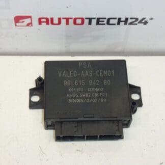
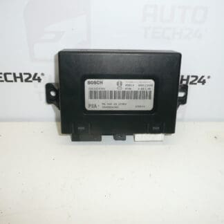
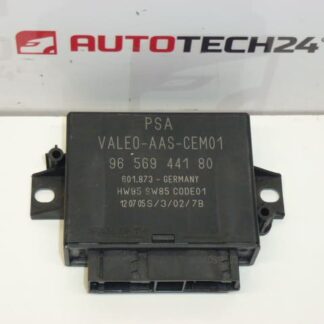
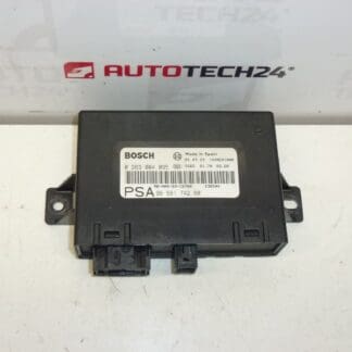
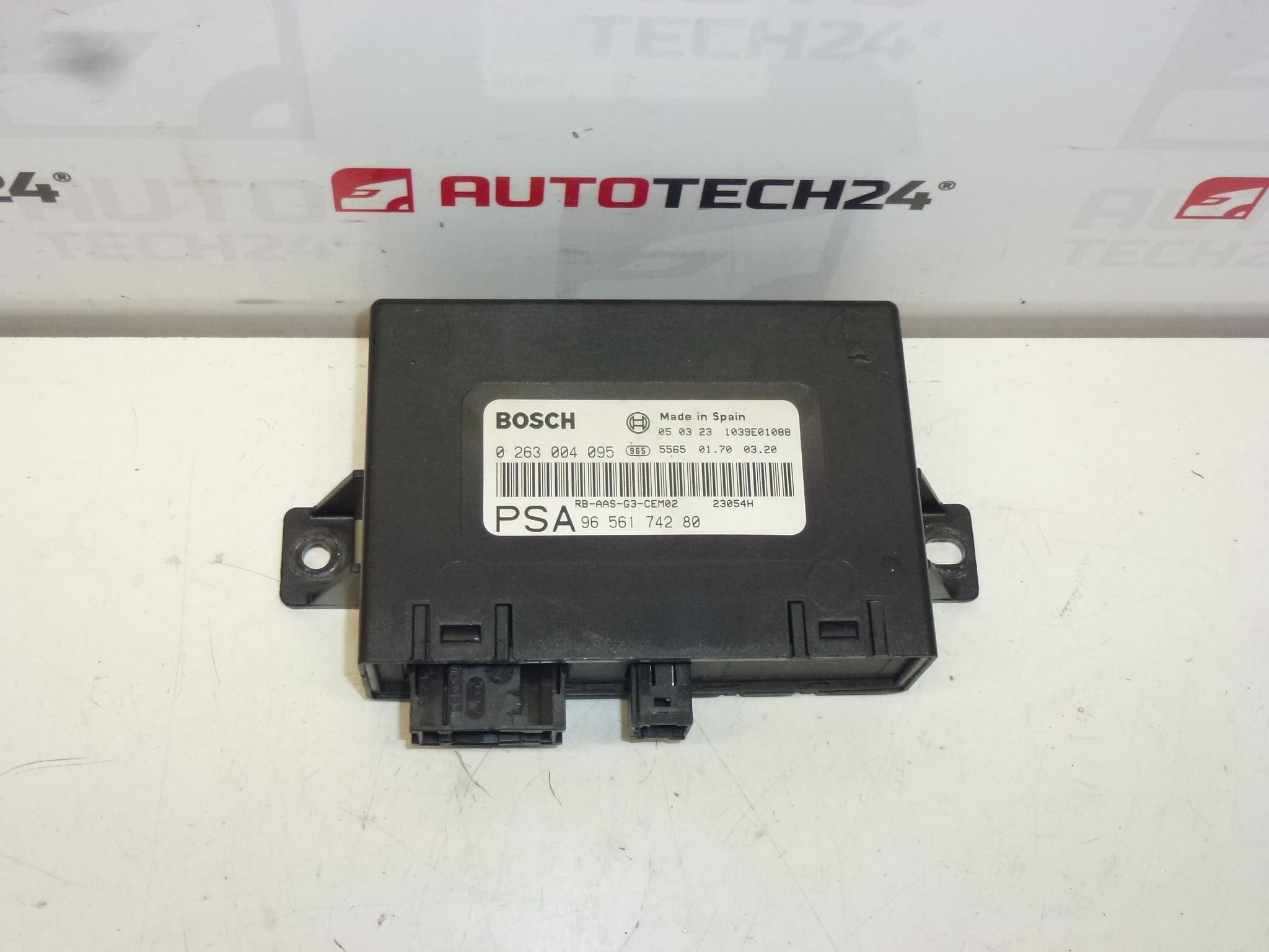
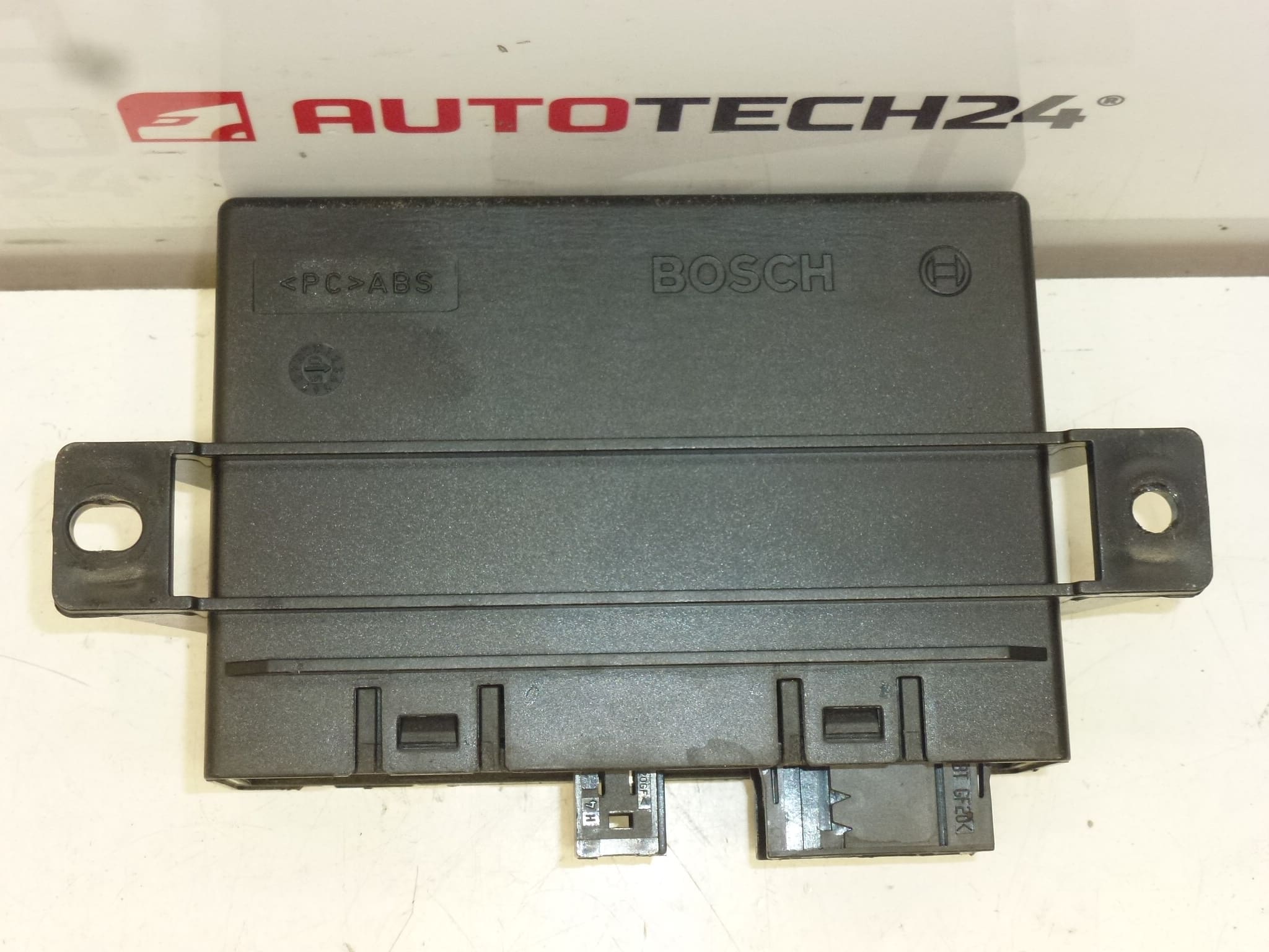
BOSCH control unit for parking assistant for Peugeot 407
Product Overview
This Bosch Parking Distance Control (PDC) ECU is a direct-fit electronic control unit designed for the Peugeot 407 parking assist system. It processes signals from ultrasonic sensors, manages the audible/visual warnings and performs basic self-diagnostics. The unit is intended for professional workshops and competent DIY mechanics who maintain or repair Peugeot 407 vehicles and search by part numbers when sourcing replacements.
Technical Information
- Manufacturer: BOSCH
- Model: Peugeot 407
- Product Codes: 0263004095
- Additional Numbers: 9656174280, 9659350680, 6590L7, 6590T5
Compatibility
Commonly fitted to Peugeot 407 models (Saloon, Coupe, SW). Ensure the part code matches the original unit when replacing to maximize plug-and-play compatibility.
Function
The PDC ECU receives inputs from the parking sensors, interprets distance information, triggers the interior/exterior warning signals (beeper, dashboard indicators) and stores fault codes for diagnostics. It also supervises sensor circuits and can indicate individual sensor failures or short circuits.
Common Symptoms Of Failure
- No parking sensor feedback (silent/no beeps) despite sensors present.
- Constant or intermittent beeping without an obstacle.
- Incorrect distance indications or one/more sensors reported as faulty in diagnostics.
- Stored fault codes related to sensor circuit faults or ECU internal errors.
Replacement Procedure
- Disconnect the vehicle battery before starting work to avoid electrical damage.
- Locate the PDC ECU (typically in the rear area of the vehicle, behind luggage compartment trim or near the rear bumper—access route depends on body style).
- Remove trim panels as required to reach the unit and unplug the multi-pin connector(s).
- Unbolt and replace the ECU with the new unit; reconnect connectors ensuring secure engagement and correct locking tabs.
- Reattach trim panels and reconnect the battery. Clear fault codes and perform a full system check with a diagnostic tool to confirm sensor operation and the absence of wiring faults.
Installation Recommendations
- Always disconnect the battery before removing or installing the unit.
- Inspect sensor cabling, connectors and fuses before replacing the ECU—damage or shorted sensors cause repeat ECU failures.
- Use appropriate diagnostic equipment to read and clear fault codes after installation. Test all sensor zones and the audible/visual warnings before final reassembly.
- Protect electrical connectors from moisture and corrosion; apply dielectric grease to connector pins if appropriate for long-term reliability.
Why This Part Fails Most Often
PDC ECUs commonly fail due to moisture ingress and connector corrosion (especially in rear-located units), impact damage from collisions to the bumper area, wiring harness faults or overcurrent conditions caused by faulty sensors. Environmental exposure and poor sealing are frequent root causes, so inspecting sensors and harnesses when replacing the ECU is essential to prevent repeated failures.