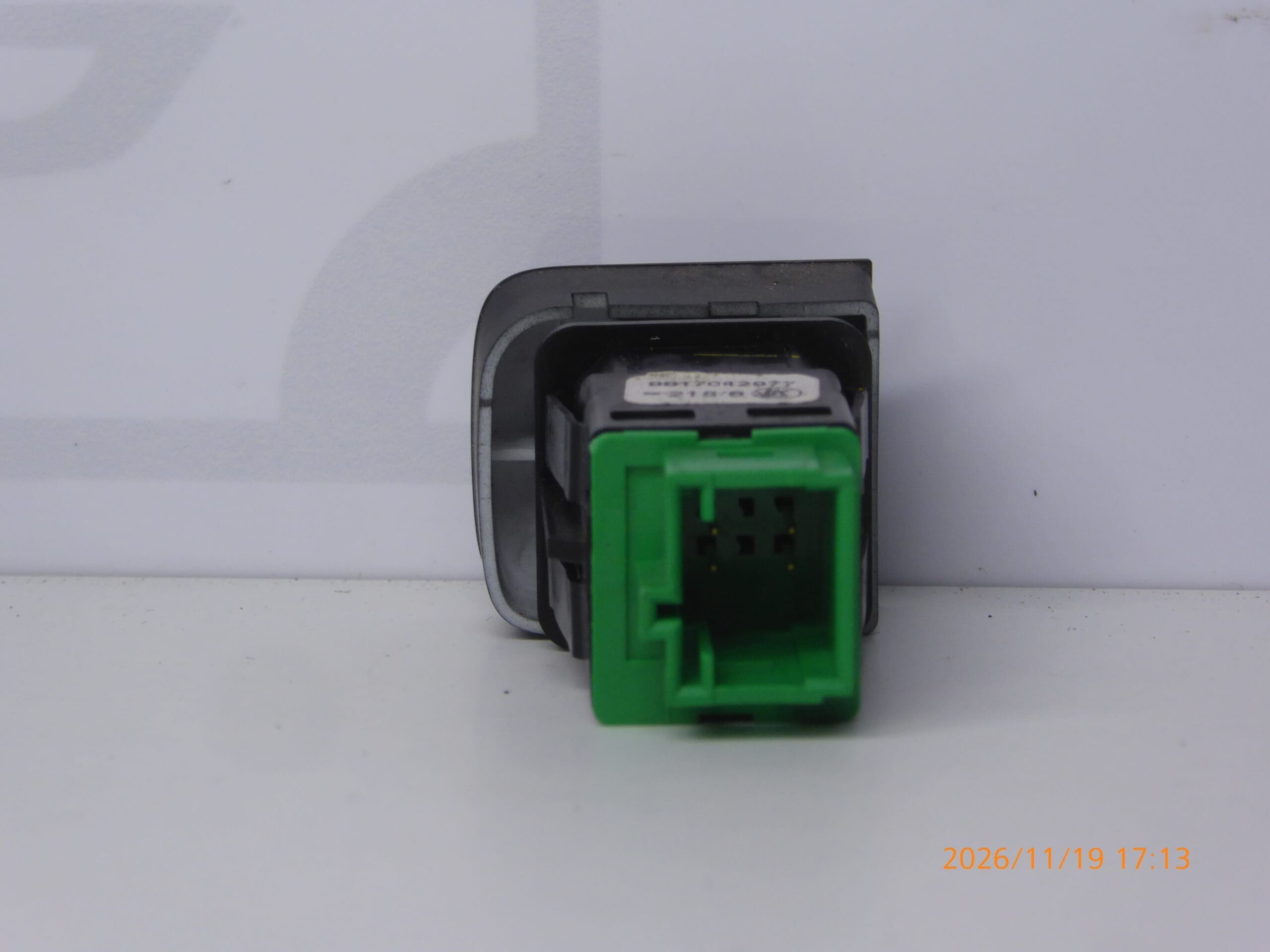
Description
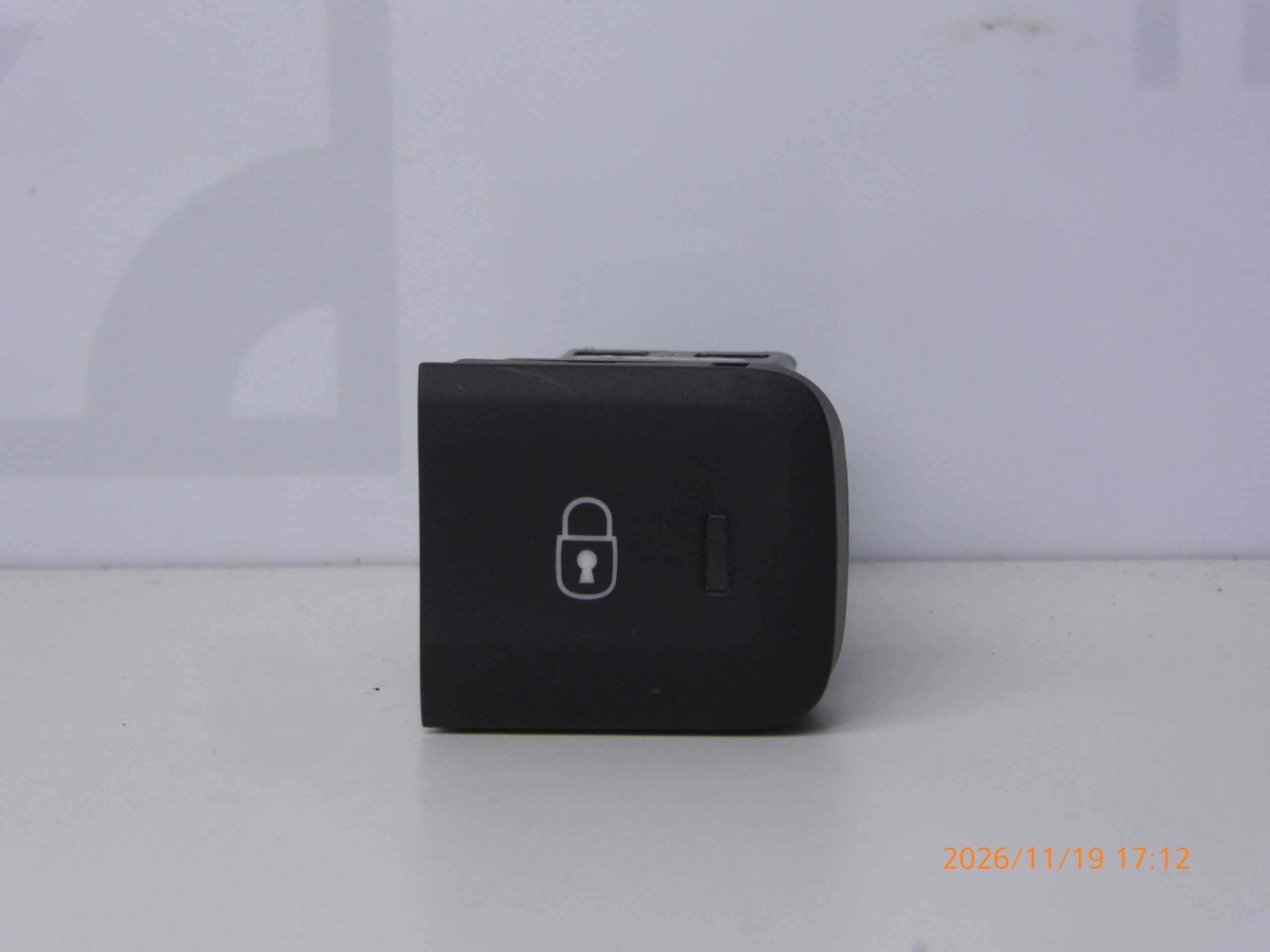
Central locking switch for CITROEN, PEUGEOT and other Stellantis models
Part description
Used central locking switch with part numbers 9817042977 and 98170429ZD is designed to control vehicle locking. When replacing a non-functional or mechanically damaged switch, it offers a practical option for retaining the original control layout.
The documentation lists the Citroën Berlingo K9, FIAT DOBLO III, OPEL COMBO E K9, PEUGEOT RIFTER and Toyota ProAce City models. When selecting a part, compare in particular the original part number, connector, shape and mounting. The model name alone is not enough to determine whether the version matches.
Technical information
- Manufacturer: not specified; the documentation lists Stellantis / CITROEN / PEUGEOT.
- Model: Citroën Berlingo K9; FIAT DOBLO III; OPEL COMBO E K9; PEUGEOT RIFTER; Toyota ProAce City.
- Additional numbers: not specified.
- Part type: central locking switch.
- Category: electrical components – other controls and switches.
- Condition: used car part.
Product codes
- Product codes: 9817042977, 98170429ZD.
Both part numbers are listed for this product. Before replacement, compare them with the number on the removed switch and also take its design into account.
Installation recommendations
The following procedure generally applies to this type of electrical switch. The exact location and method of accessing and releasing the switch depend on the specific vehicle model and version. Follow the manufacturer’s service procedure; the documentation does not specify these details.
1) Before installation
- Compare the part numbers, dimensions, front face, mounting and connector shape, including the contact layout.
- Inspect the used switch: the plastic housing must not be damaged in a way that prevents it from being secured, and the contacts must not be bent or corroded.
- Check that the control element moves freely and shows no obvious mechanical damage.
- Also check the vehicle connector and wiring before replacement. A central locking fault may not be caused by the switch itself.
2) Tools and materials required
- Plastic trim removal tools.
- Hand tools suited to the actual fasteners.
- A flashlight, clean cloth and protection for surrounding visible surfaces.
- If needed, a product intended for electrical contacts and suitable for the surrounding materials.
3) Step-by-step installation procedure
- Secure the vehicle against movement and prepare access to the work area.
- Keep the key outside the vehicle and ensure you can access the interior in case it is unexpectedly locked.
- Switch off the ignition and electrical accessories. Follow the manufacturer’s procedure for allowing the electronics to enter sleep mode and safely disconnecting the battery before working on electrical connectors.
- Inspect how the surrounding trim is secured. Release covers only at the designated points and do not force them off.
- Once the switch is accessible, note its orientation and the routing of the wiring, for example by taking a photograph.
- Release the switch using the appropriate tool and carefully slide it out without putting tension on the wires.
- Release the connector lock and disconnect it by pulling on its housing, not on the wires.
- Compare the two switches side by side. If the connector or mounting differs, do not proceed by modifying the connector or plastic parts.
- Inspect the vehicle connector and accessible wiring. Clean off any dirt appropriately; have damaged or loose contacts repaired professionally first.
- Connect the replacement switch, secure the connector and fit the part into its original mounting. The wiring must not be pinched or stretched.
- Reinstall the trim and fasteners. Restore the power supply according to the manufacturer’s procedure and check that the switch works.
4) Post-installation checks and function verification
- With the vehicle stationary, check the central locking’s response to each switch command, as applicable to the vehicle’s equipment.
- Check that the switch is firmly secured, moves freely and that the surrounding trim fits correctly.
- Keep the key outside the interior while performing the test. Consider the risk of accidentally locking the vehicle before testing.
- If the fault persists, proceed with diagnosing the power supply, wiring and central locking system instead of repeatedly replacing the switch without first identifying the cause.
- A stationary test is usually sufficient for a basic check of this type of switch; perform any additional checks in accordance with the vehicle’s service instructions.
5) Common installation errors and how to avoid them
- Choosing based on appearance alone: also compare the part numbers, connector and mounting.
- Breaking plastic retaining clips: first determine how they are released and use appropriate removal tools.
- Pulling on the wires: disconnect the connector only by its housing after releasing the lock.
- Connector not fully engaged or wiring pinched: check that the connector is secured and the wires are routed freely before closing the trim.
- Confusing a system fault with a switch fault: rule out visible damage to the connector and wiring before installation.
Reasons why the part may become damaged
The following causes of damage may generally occur with central locking switches. This is not a description of faults identified on this specific unit.
- Mechanical wear from frequent use, which may lead to unreliable switching or the control element sticking.
- Excessive pressure or impact, which may damage the button, cover or retaining clips.
- Ingress of liquids and dirt, which may result in poor contact, corrosion or restricted button movement.
- Careless removal, especially prying with an unsuitable tool and pulling on connected wires.
- Loose or damaged connector, which may cause intermittent operation and put strain on the electrical connection.