Description
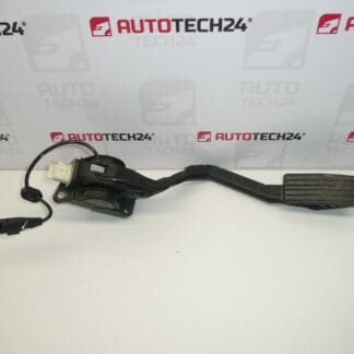
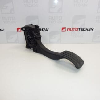
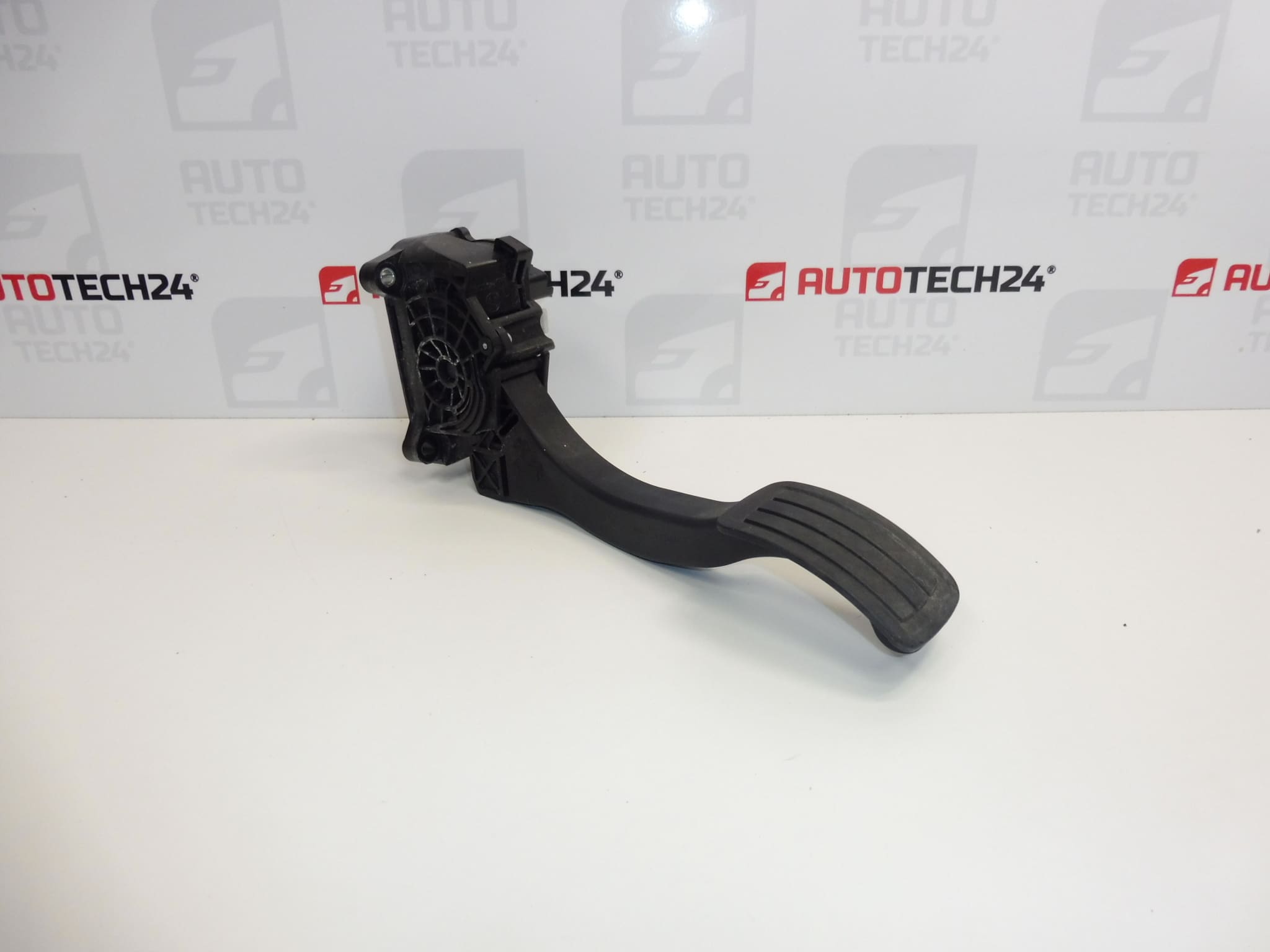
BOSCH accelerator pedal for Stellantis vehicles
Part description
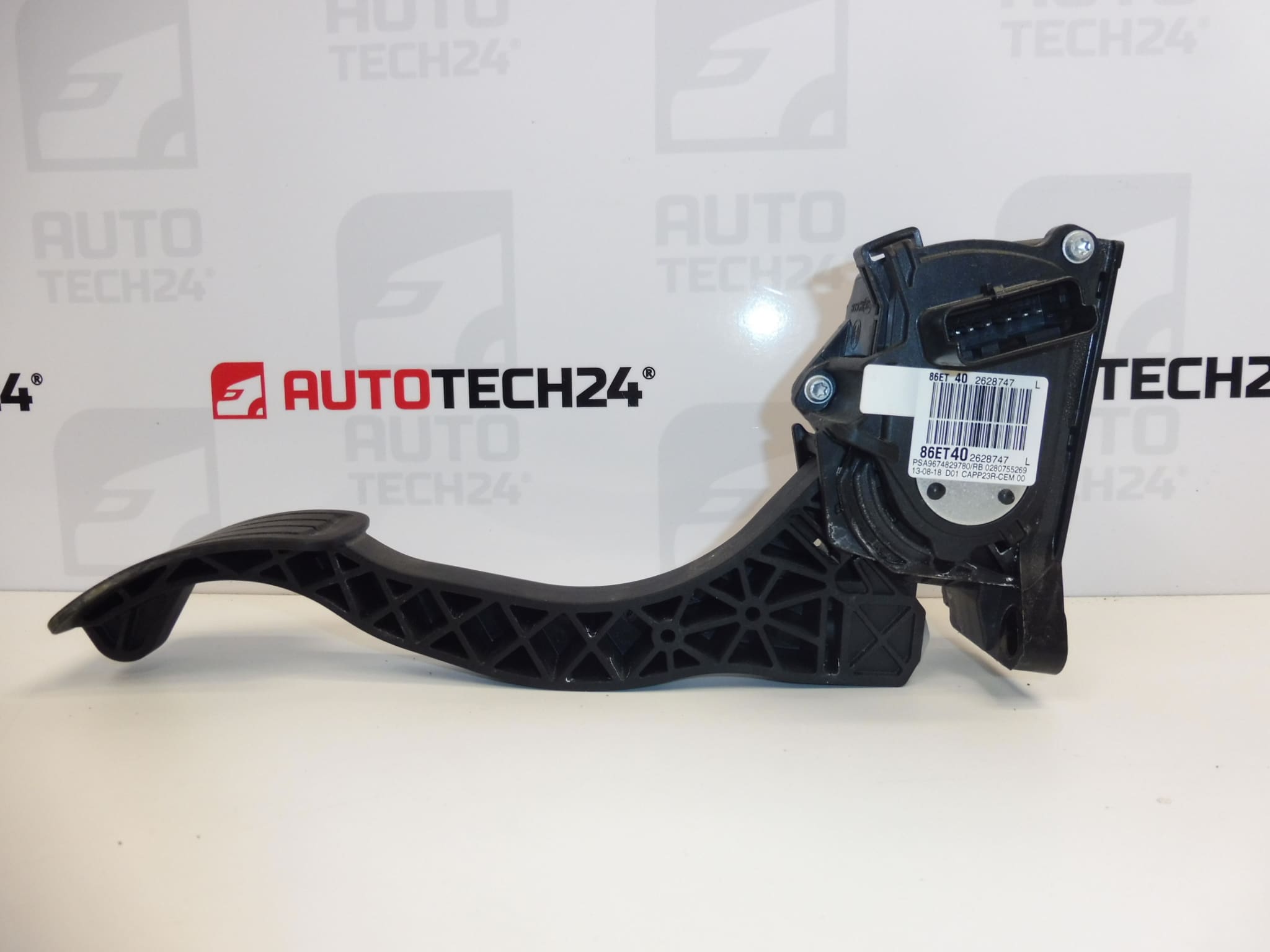
Used BOSCH accelerator pedal with product numbers 9674829780 and 9838028180 is designed for electronic control of acceleration demand. In this type of part, the pedal position sensor sends information about pedal depression to the control unit. Proper operation is important for a smooth and predictable vehicle response when the accelerator is pressed.
This is an option for replacing a faulty pedal when repairing a vehicle without purchasing a new part. When selecting one, rely primarily on the markings on the original part, connector design and mounting points. The list of models in the source material does not in itself indicate compatibility with all their variants.
Technical information
- Manufacturer: BOSCH
- Model: CITROEN BERLINGO III; Citroën Berlingo K9; FIAT DOBLO III; OPEL COMBO E K9; PEUGEOT PARTNER III; PEUGEOT RIFTER; Toyota ProAce City
- Part type: accelerator pedal with electronic position sensing
- Condition: used automotive part
- Product numbers: 9674829780, 9838028180
- Other numbers: not specified
- Years and engine variants: not specified
Product codes
- Product codes: 9674829780, 9838028180
Both numbers are listed in the source material for the pedal offered. Compare them with the markings on the removed part; visual similarity alone does not necessarily mean that the electrical design is the same.
Installation recommendations
The following procedure is general guidance for electronic accelerator pedals. The exact removal procedure, access to the mounting points and any adjustment after replacement depend on the specific model and vehicle configuration. Follow the manufacturer’s service procedure.
1) Before installation
- Compare the product numbers, pedal shape, mounting points and connector design with the old part.
- Check the housing, pedal arm and mounting parts. They should not be cracked or deformed.
- Check that the pedal moves smoothly and returns to its starting position on its own. Do not use excessive force.
- Inspect the contacts and connector lock. Look for corrosion, moisture, bent contacts or signs of overheating.
- Before replacement, also check the wiring and connector in the vehicle, as the fault may not be in the pedal itself.
2) Tools and materials required
- Standard hand tools appropriate for the fasteners used.
- A suitable tool for carefully removing any covers and a flashlight.
- A clean cloth and, if needed, a product intended for cleaning electrical contacts.
- A diagnostic tool suitable for the vehicle, especially for checking the pedal signal and fault memory.
3) Step-by-step installation procedure
- Secure the vehicle against movement and remove any objects or floor mats that could restrict pedal movement.
- If possible, read and record any faults and available pedal position data before removal.
- Switch off the ignition and, following the manufacturer’s instructions, allow the electronics to enter sleep mode. Disconnect the battery according to the service procedure for the specific vehicle.
- Access the pedal mounting points. Carefully remove any obstructing covers without damaging clips or wiring.
- Note the original routing of the wiring harness so it can be returned to the same position.
- Release the electrical connector lock and disconnect it by gripping the connector body, not by pulling on the wires.
- Undo the fasteners, support the pedal and remove it. Check the condition of the mating and mounting surfaces.
- Compare the two parts once more and remove any dirt from the installation area. Do not introduce liquids into the pedal mechanism or electrical components.
- Position the replacement pedal without putting it under strain and secure it according to the manufacturer’s specifications. Do not compensate for incorrect positioning by tightening it forcibly.
- Connect the connector until the lock engages and route the wiring so that it is not stretched, rubbed or interfering with pedal movement.
- Refit any removed covers, restore power according to the manufacturer’s instructions and check that the pedal moves freely. Carry out any required adjustment using suitable diagnostic equipment.
4) Checks after installation and function verification
- With the engine off, check that the pedal moves smoothly and returns properly, and that there is sufficient clearance for its movement, including correct positioning of the floor mat.
- If the diagnostic tool can display pedal position, check that the readings change smoothly while slowly depressing and releasing the pedal.
- Check the fault memory. Do not clear any faults without assessing their cause.
- After a successful stationary check, verify the vehicle’s response with a short test drive in a safe place. If the accelerator response is erratic, the pedal sticks or a warning message appears, stop driving and investigate the fault.
5) Common installation errors and how to avoid them
- Confusing pedals that look similar: compare the markings, connector and mounting points.
- Connector not secured properly: check that it is fully seated and that the lock works, not just that the connector is plugged in.
- Wiring pinched or stretched: keep the original routing and check it after refitting the covers.
- Damage to the mounting points from overtightening: follow the vehicle manufacturer’s procedure and specified tightening torque.
- Replacement without investigating the cause: also check the contacts and wiring to ensure the original problem is resolved.
Reasons why the part may become damaged
For electronic accelerator pedals in general, the following causes of damage or malfunction are possible. This is not a description of the condition of the part being offered.
- Long-term mechanical stress on moving parts and the return mechanism.
- Moisture and dirt, which can damage electrical contacts or affect the mechanism’s operation.
- Damaged connector or wiring, for example due to pulling on the wires, chafing or careless removal.
- Mechanical impact or overload, which can crack the housing, arm or mounting points.
- Position sensing fault, which can result in an erratic or implausible signal to the control unit.