Description
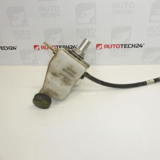
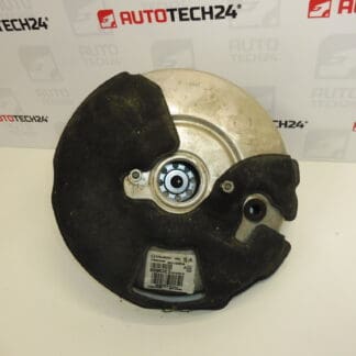
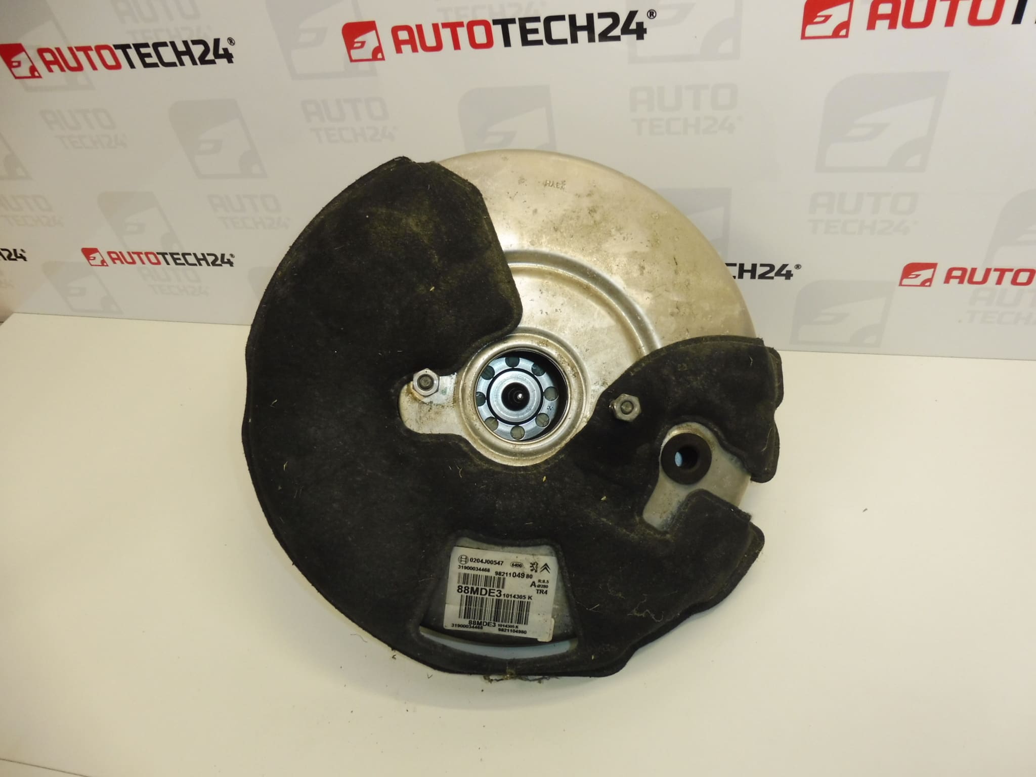
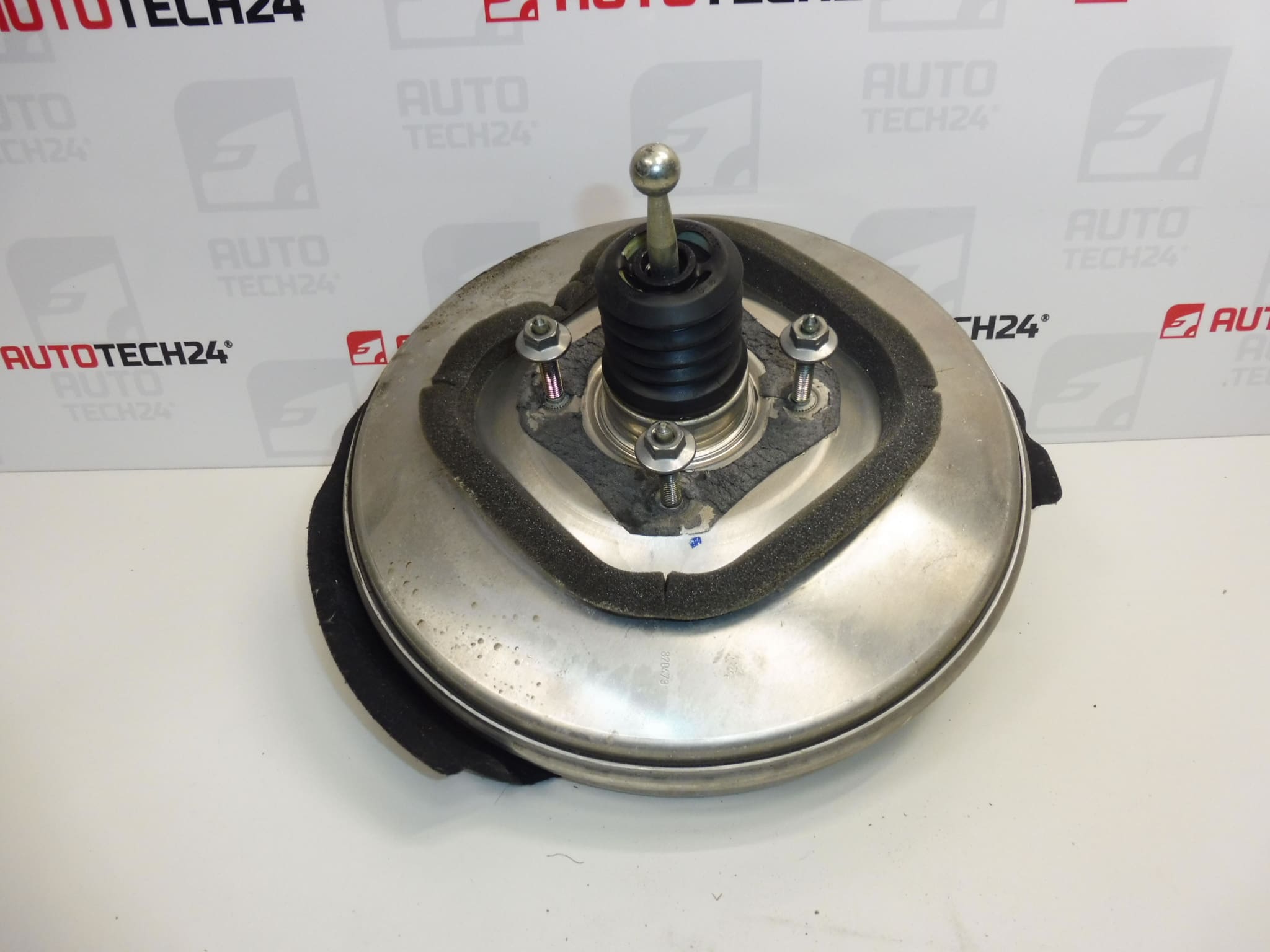
BOSCH brake booster for Stellantis vehicles
From a vehicle with 33,000 km mileage
Part description
Used BOSCH brake booster for Stellantis Group vehicles, identifiable by part numbers 9821104980, 0204J00547 and 1635255280. The brake booster reduces the force needed to press the brake pedal and contributes to comfortable brake operation. Correct functioning of this component is important for safe braking.
The part comes from a vehicle with 33,000 km mileage and offers a replacement for a faulty brake booster with a used part whose donor vehicle’s mileage is known. The supplied information lists the Citroën Berlingo K9, Peugeot Partner III, Peugeot Rifter, Opel Combo E K9 and Fiat Doblo III models. When selecting a part, compare not only the part numbers but also the mounting points, connections and control mechanism design with the original part.
Technical information
- Manufacturer: BOSCH
- Model: Citroën Berlingo K9; FIAT DOBLO III; OPEL COMBO E K9; PEUGEOT PARTNER III; PEUGEOT RIFTER
- Part type: brake booster
- Vehicle group: Stellantis
- Condition: used part
- Donor vehicle mileage: 33,000 km
- Other numbers: not specified
The model names are taken from the supplied labels. Specific model years, engine types and brake system variants are not listed; therefore, the model name alone is not sufficient to determine whether the part is suitable.
Product codes
- Product codes: 9821104980, 0204J00547, 1635255280
The numbers listed can be used to search for the brake booster and compare it with the markings on the original part. The supplied information does not specify the relationship between the individual numbers or the extent to which they are interchangeable.
Installation recommendations
The following procedure is general and typical for replacing a brake booster. Access to the part, connection method and exact steps depend on the specific model and vehicle configuration. This is a safety-critical component: installation requires appropriate experience and compliance with the manufacturer’s service documentation.
1) Before installation
- First determine the cause of the fault. A hard brake pedal or weak assistance does not necessarily mean that the brake booster itself is damaged.
- Compare the part numbers, housing shape, mounting points, connection to the master brake cylinder, control rod and connections with the old part.
- Inspect the used part: check for deformation, cracks, corrosion, threads, any seals present and signs of fluid.
- If there is damage or a difference in design, stop the installation and arrange for a professional assessment.
2) Tools and materials required
In general, prepare suitable hand tools, a torque wrench, lighting, protective gloves and clean materials to protect disconnected connections. If the work requires opening the hydraulic circuit, equipment for bleeding the brakes will also be needed. Determine the requirements for sealing and locking components according to the service documentation for the specific vehicle.
3) Step-by-step installation procedure
- Park the vehicle on a level surface, secure it against movement and review the prescribed replacement procedure.
- Switch off the ignition. Secure the electrical system and release residual energy in the brake assistance system as specified by the manufacturer.
- Remove the components necessary to gain access. Record the routing of connections and the position of locking components, for example by taking photographs.
- Clean the area around the joints to prevent dirt from entering the connected systems when they are disconnected.
- Depending on the configuration, disconnect the brake booster connections. Release hoses, any connectors and their locks without using force.
- Release the master brake cylinder according to the service procedure. If it can remain connected to the lines, support it securely; do not leave it hanging from the lines. Protect any open hydraulic connections from contamination.
- Disconnect the control mechanism, release the brake booster mounting and carefully remove the part without damaging surrounding components.
- Compare the two parts side by side and check the mating surfaces. Do not adjust the rod length or setting by guesswork.
- Position the replacement brake booster, secure it and correctly fasten the control linkage. Tightening and any adjustment must be performed strictly according to the vehicle manufacturer’s specifications.
- Reinstall the master brake cylinder, connections and all other removed components. Check that no lines are pinched, stretched or kinked.
- If the hydraulic circuit was opened, bleed it using the prescribed procedure. Before moving the vehicle, complete the leak check and check that all connections are secure and the brakes function correctly.
4) Post-installation checks and test drive/function verification
With the vehicle stationary, check the brake assistance function, pedal return and tightness of the affected connections according to the service documentation. Also check that the brakes do not remain applied after the pedal is released. Only carry out a test drive after the stationary checks have been completed successfully, initially at low speed in a safe area away from normal traffic. If the pedal behaves unusually, fluid is leaking or braking is inadequate, do not use the vehicle and have the fault rectified.
5) Most common installation errors and how to avoid them
- Confusing similar versions: compare the markings and design details, not just the appearance of the housing.
- Replacing the part without identifying the cause of the fault: check related parts of the brake assistance system before installation.
- Incorrect rod adjustment: follow the service procedure and do not make adjustments by guesswork.
- Straining the brake lines: support the released cylinder and do not bend the lines by force.
- Damaged seals or unsecured connections: during reassembly, check the fit, condition of the sealing surfaces and all locking components.
- Skipping bleeding or a functional check: after opening the hydraulic system, complete the prescribed bleeding procedure and verify the function of the entire affected system before driving.
Reasons why the part may become damaged
In general, the following factors may cause damage to a brake booster. This is not a description of any faults found on the offered part:
- Aging seals and wear of moving parts, which may lead to loss of tightness or irregular operation.
- Moisture and corrosion affecting the housing, connections or control mechanism.
- Brake fluid entering from a leaking master cylinder, where the assembly design allows this.
- Mechanical damage resulting from an accident, dropping the part, improper handling or forced installation.
- Incorrect adjustment or excessive strain on the control mechanism, which interferes with proper operation.
In vacuum systems, similar fault symptoms may also be caused by leaking hoses, a faulty check valve or a problem with the vacuum source. It is therefore important to assess the system as a whole before replacement and address any underlying cause of the damage.