Description
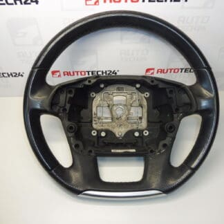
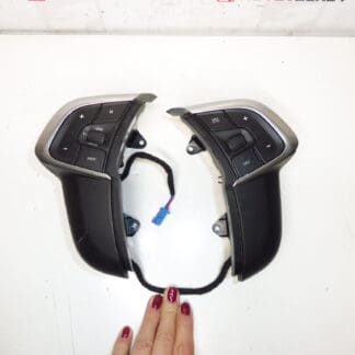
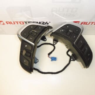
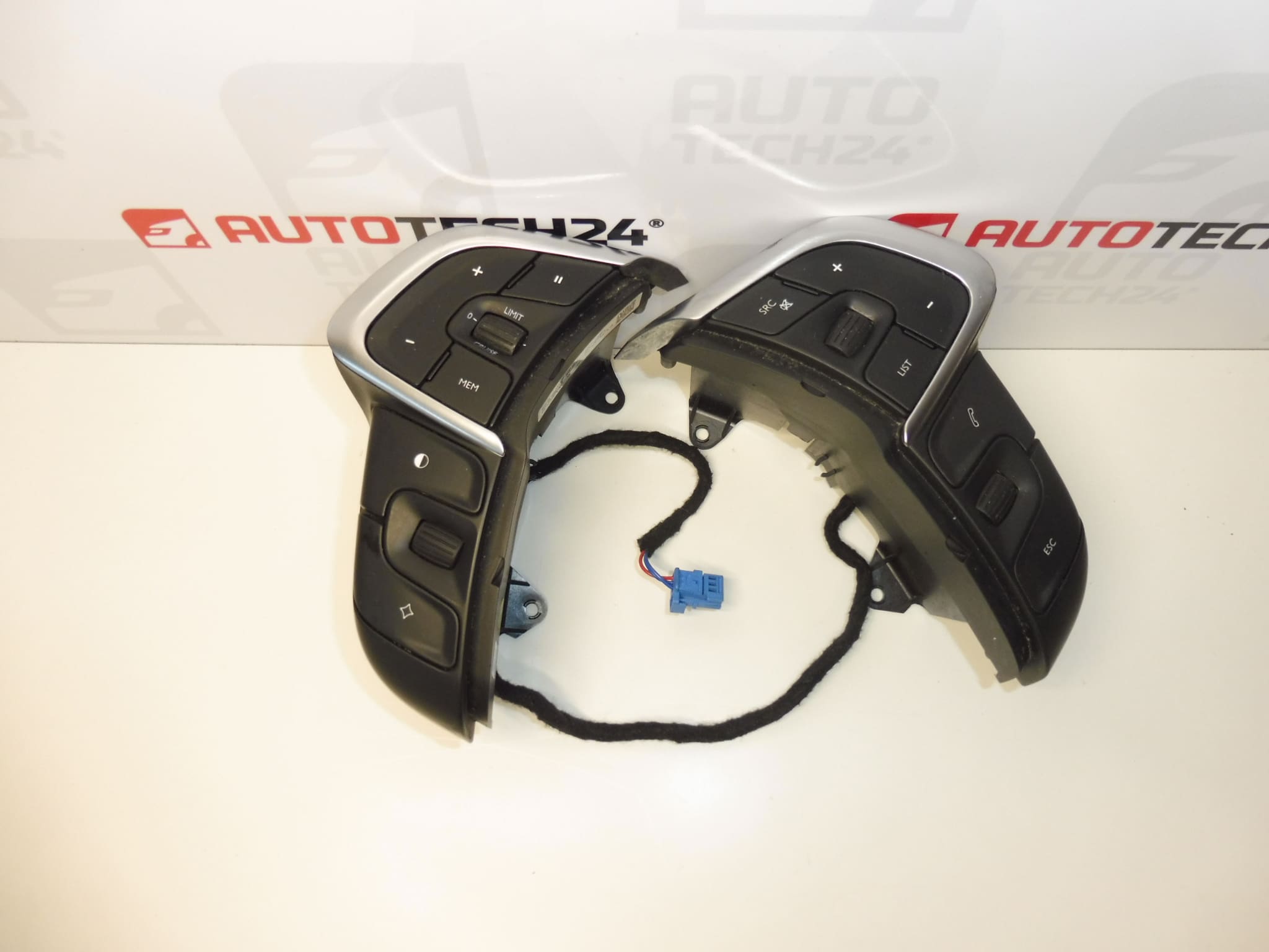
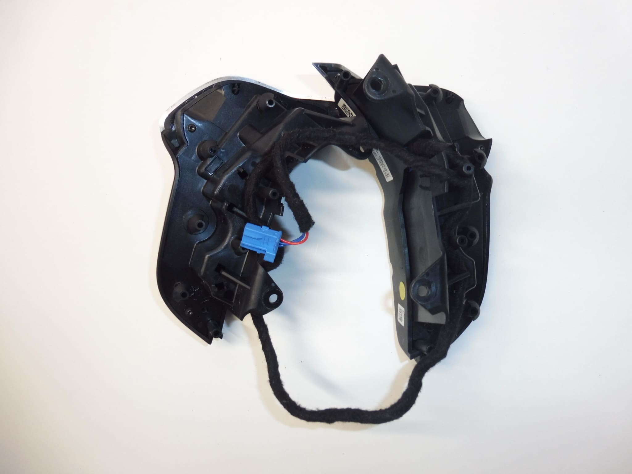
Integrated steering wheel switch module for Citreon C4 II and DS4 cars
HZD color – BLACK MISTRAL
Part description
The used Citroen C4 II and DS4 steering wheel control is an integrated switch module designed to replace a damaged or non-functioning control. Allows operation of functions assigned to steering wheel switches; their specific range depends on the design and equipment of the car.
The part is listed under the numbers 96720514ZD and 98094655ZD and in the color version HZD – BLACK MISTRAL. When choosing, compare the markings of the original module, the location and symbols of the switches, connectors and fasteners. The used module is a practical option for repair if the fault lies precisely in the steering wheel control.
Technical information
- Manufacturer: not specified; the documents indicate the name Stellantis CITROEN PEUGEOT.
- Model: Citroen C4 II, DS4.
- Part Type: integrated steering wheel switch module.
- Design: used car part.
- Color: HZD – BLACK MISTRAL.
- Category: interior, steering wheels.
- Other numbers: not specified.
Product codes
- Product codes: 96720514ZD, 98094655ZD.
- Models according to labels: Citroen C4 II, DS4.
Product numbers make it easy to locate the part. The documents list both codes, but do not describe their interchangeability for individual car designs.
Installation recommendations
In general, the following procedure applies to this type of part. The exact method of accessing the module, unlocking the connectors and fixing it depends on the specific model and design of the steering wheel. The work may interfere with the proximity of the airbag; if its removal requires a service procedure, entrust this operation to a suitably qualified person.
1) Before assembly
- Verify that the switch module is causing the problem, not the wiring, connector, or other part of the control system.
- Compare the product designation, module shape, symbols and button placement, connectors and mounts with the original piece.
- Inspect the used part: check for cracks, damage to the latches, the condition of the contacts and any signs of moisture.
- Gently test the mechanical operation of the switches. They should not jam or require forceful compression.
- Prepare a service procedure for a specific car, especially the rules for disconnecting the battery and safe work around the airbag.
2) Necessary tools and materials
- Hand tools and screw attachments corresponding to the joints used.
- Plastic disassembly tools for gentle release of covers.
- Flashlight, clean cloth and container for discarded fasteners.
- If necessary, means suitable for electrical contacts and diagnostic equipment for the given vehicle.
3) Step-by-step assembly procedure
- Stop the vehicle safely, secure against movement and switch off the ignition.
- Follow the manufacturer’s procedure for putting the electronics to rest, disconnecting the battery and the prescribed waiting time before working around the airbag.
- According to the service procedure, access the module. Do not force the covers loose; first find out how to secure them.
- If access requires tampering with the airbag system, proceed only with the necessary qualifications and according to the manufacturer’s instructions. Do not perform improvised electrical measurements on the airbag connectors.
- Before disconnecting, make a note of the wiring route and the position of the connectors, such as a photo.
- Unfasten the original module, unlock the appropriate connectors and disconnect them by their body, not by pulling on the wires.
- Remove the original module and check the accessible wiring, contacts and seating surfaces. Remove detected damage first.
- Compare both modules again. If the connectors, mounts or arrangement of the controls are different, do not adjust the assembly by force or modification of the wiring.
- Connect the corresponding connectors, check their security and seat the replacement module without tension. Route the cabling so that it is not pinched.
- Secure the module in the prescribed manner and return the disassembled parts according to the service procedure. Do not overload the plastic handles.
- After complete assembly, connect the battery according to the manufacturer’s instructions and perform a function check.
-
4) Post-assembly checks and test drive/function verification
- First, test the individual switches and the corresponding reactions of the controlled functions on a stationary vehicle.
- Check that the buttons move freely, the covers fit properly and that no part is loose.
- Verify that there is no unusual warning message after the impact, especially related to the airbag. Diagnose the possible fault first.
- Do a short test drive only after a successful on-site inspection. Verify functions available only while driving safely, without distracting from driving.
5) The most common assembly mistakes and how to avoid them
- Choose only by appearance: also compare the markings, connectors, mounting and design of the switches.
- Breaking latches: before prying, find out the direction and method of unlocking them.
- Wires pulled out or connector not clicked: hold the connectors by the body and check their security after connection.
- Pinch wiring: keep the original wiring and inspect before covering.
- Replacement without finding the cause of the defect: damaged wiring or contacts can cause the same symptoms as a defective module.
- Failure to follow the safety procedure: when working around the airbag, do not improvise and respect the manufacturer’s instructions.
Reasons why the part is damaged
Steering wheel switch modules can generally experience the following causes of damage. It is not a description of the ascertained condition of the offered piece.
- Wear from use: repeated pressing can gradually deteriorate the mechanical operation and reliability of the contacts.
- Dirt and moisture: dust, grease or runny detergent can lead to stuck buttons or electrical contact disruption.
- Rough handling: Excessive pressure or impact can damage the controls, housing or fasteners.
- Aging of materials: long-term thermal stress can contribute to the brittleness of plastic parts.