Description
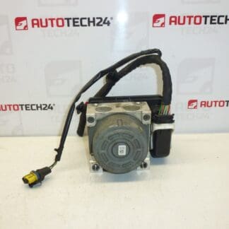
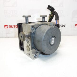
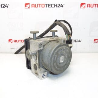
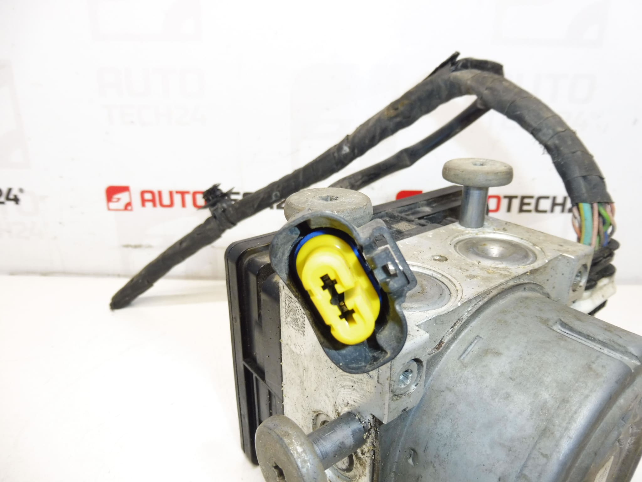
Control Module, ABS Pump, ESP Unit, ATE ABS Block
Fits Peugeot 301 and is compatible with Peugeot 208 and Citroën C-Elysée
Includes Wiring Harness for easy installation
Are you looking for a reliable and fully functional control module for your ABS and ESP system? We offer a used but fully operational module designed for Citroën and Peugeot vehicles, ensuring safe and stable operation of your car. The ECU ABS ESP module with reference numbers 9817031680, 10.0915-3947.3, and 1682592280 is primarily suitable for Peugeot 208, Peugeot 301, and Citroën C-Elysée models.
This part is crucial for the proper functioning of your vehicle’s ABS braking system and electronic stability program (ESP). It allows fast and effective vehicle response during critical driving situations, thereby enhancing safety on the road. The package includes a complete wiring harness to simplify installation into your vehicle.
Technical Information
Manufacturer: ATE
Model: Compatible with Peugeot 208, Peugeot 301, Citroën C-Elysée
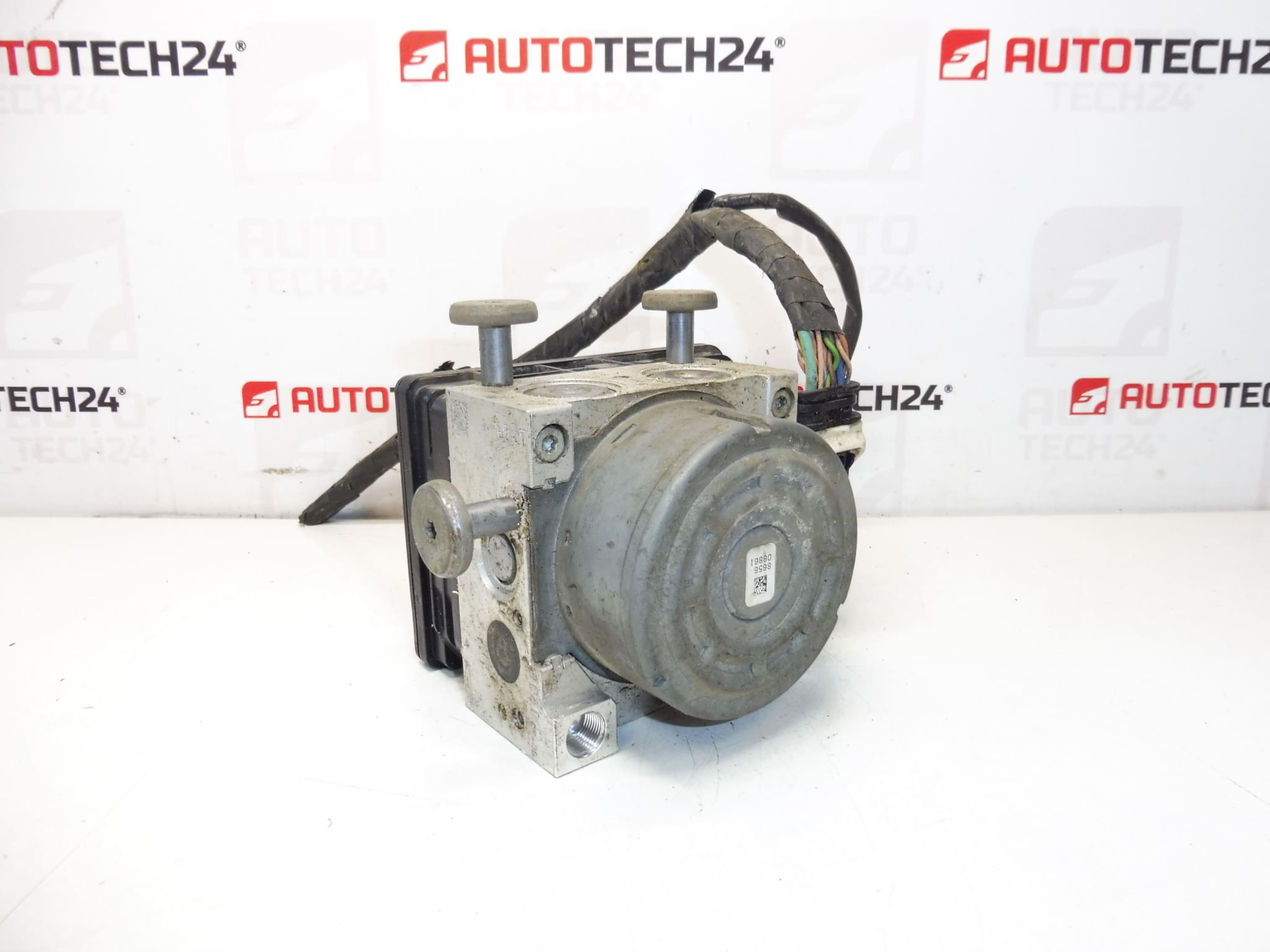
Product Codes: 9817031680, 10.0915-3947.3, 1682592280, 1616784480
Additional Numbers: Specifications compliant with OEM requirements for Citroën and Peugeot models
This ECU module plays a vital role in controlling the ABS pump and ESP unit, ensuring efficient brake modulation and vehicle stability control. Failures of these modules usually occur due to internal electronic faults or hydraulic pump wear caused by prolonged use or contamination. Typical signs of malfunction include ABS warning lights, ESP warning lights, or reduced braking efficiency.
Replacement is generally straightforward, especially with the included wiring harness, but it requires careful handling and proper diagnostics to ensure compatibility. Regular maintenance and timely replacement of the ECU ABS ESP module can prevent costly repairs and ensure optimal vehicle safety.
This ECU ABS ESP module is an excellent choice for professional mechanics and DIY enthusiasts working on Citroën and Peugeot vehicles, delivering high reliability and seamless fitment without compatibility issues.