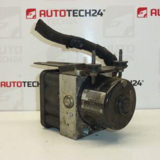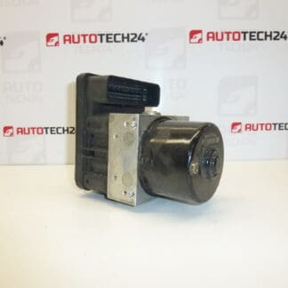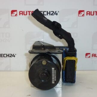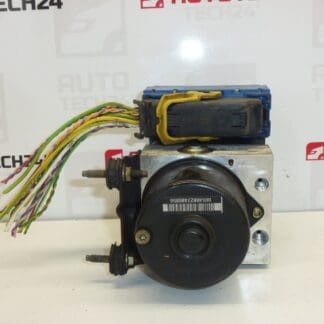
Description
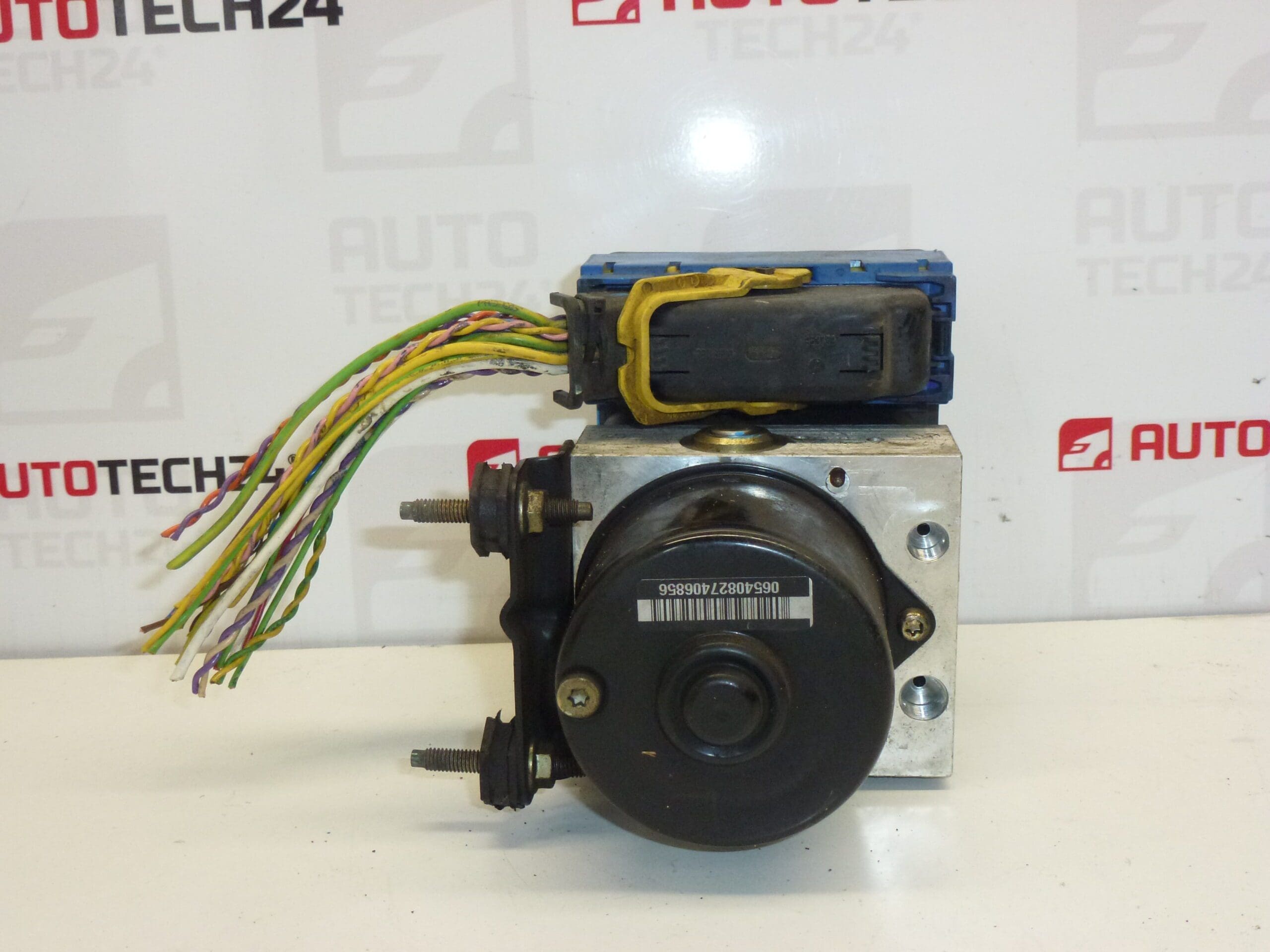
Control Module, Pump, Unit, ABS/ESP Block ATE Citroën C5. From 2006 2.0 HDi RHR Estate. Includes A Section Of Wiring Harness.
This ABS/ESP pump assembly by ATE is a direct-fit hydraulic and electronic unit commonly found on Citroën C5 II vehicles. Designed For Professional Workshops And Skilled DIYers, It Restores Anti-Lock Braking And Electronic Stability Functions When The Original Module Fails. The Unit Includes A Short Length Of Wiring Harness To Facilitate Replacement And Matching To The Vehicle Connector.
Function And Benefits
The ABS/ESP Pump Module Regulates Brake Hydraulic Pressure During ABS And ESP Interventions. It Contains An Electric Motor-Driven Pump, Solenoid Valves And An Electronic Control Module That Interfaces With Wheel Speed Sensors And The Vehicle CAN Network. Replacing A Faulty Unit Restores Reliable Brake Pressure Modulations, Improves Vehicle Stability Under Heavy Braking Or Slippery Conditions, And Clears Warning Lights Related To ABS/ESP Malfunctions.
Technical Information
- Manufacturer: ATE (Fits Stellantis PEUGEOT/CITROËN Applications)
- Model: Citroën C5 II (Example Fitment: 2006 2.0 HDi RHR Estate)
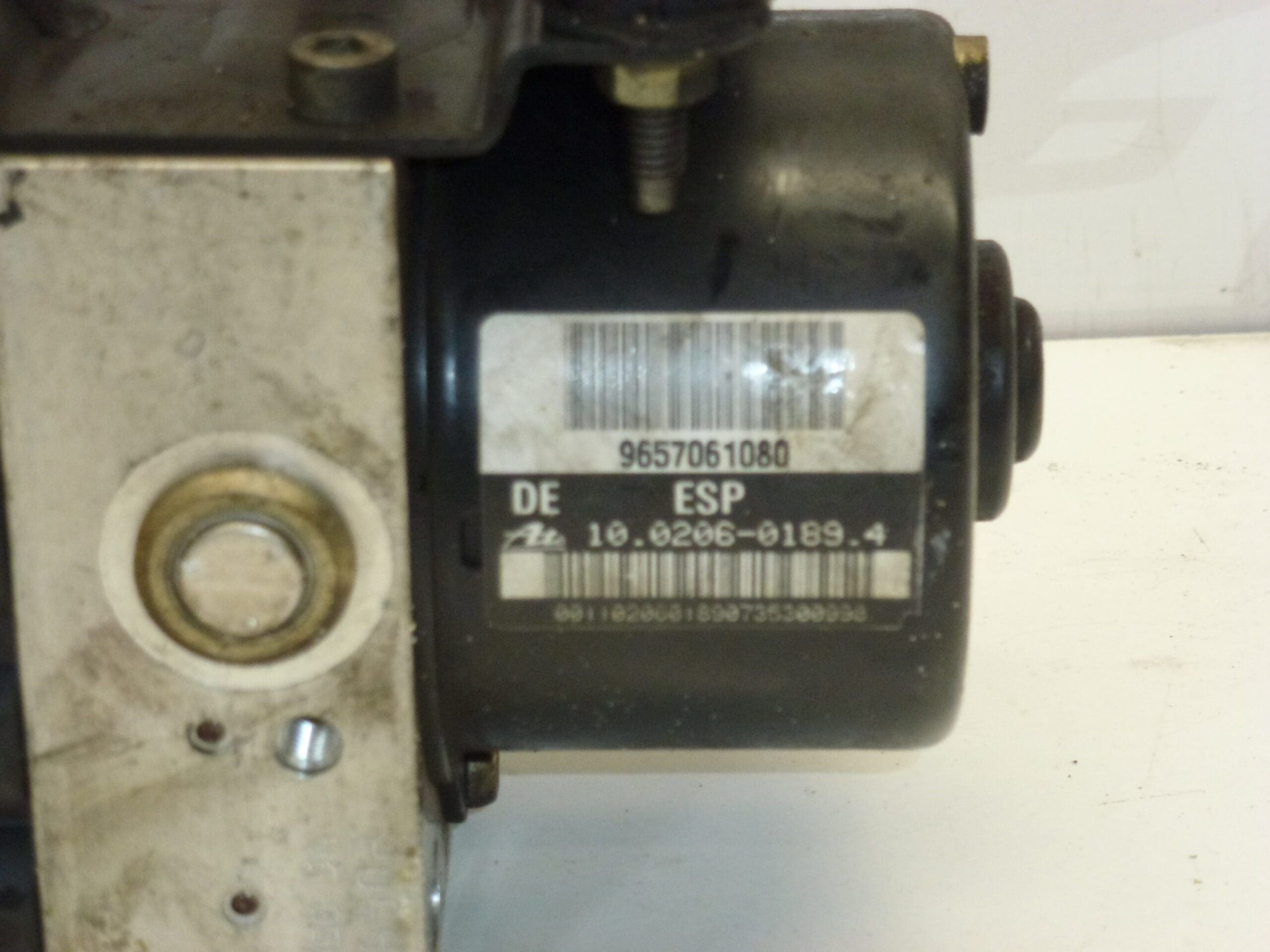
- Product Codes: 9657061080; 10.0960-1147.3; 10.0206-0189.4
- Other Numbers: 4542F0; 4542F1; 4541G1; 4541G2; 4541F0
Compatibility And Fitment Notes
Intended For Citroën C5 II Vehicles Matching The Above Part Numbers, Especially Diesel 2.0 HDi RHR Estate Variants From Around 2006. Verify That The Vehicle Uses The Same Product Codes Listed Above To Ensure Correct Fitment. Professional Verification Of Connector Layout And Mounting Points Is Recommended Before Installation.
Installation Recommendations
- Disconnect The Battery Before Starting To Prevent Electrical Damage.
- Secure The Vehicle And Remove Any Underbody Covers Or Brackets To Access The ABS Unit.
- Retain The Supplied Section Of Wiring Harness And Match Connector Pins Carefully; Replace Any Corroded Pins.
- After Mechanical Installation, Perform Full Brake System Bleeding To Remove Air From Lines.
- Use A Diagnostic Tool To Clear Fault Codes And Initialize/Calibrate The ABS/ESP System If Required By The Vehicle.
- Follow Manufacturer Torque Specifications For Mounting Fasteners And Observe Brake Fluid Cleanliness.
Most Common Cause Of Failure
These Modules Typically Fail Due To Corrosion Of Electrical Contacts, Water Ingress, Or Internal Pump Wear After Years Of Service. Electrical Faults From Damaged Wiring Or Faulty Connectors Can Cause Intermittent Operation Or Complete Loss Of ABS/ESP Function. Contamination In The Brake Fluid And Prolonged Exposure To Road Salt Accelerate Mechanical And Electrical Degradation.
When To Replace
Replace The Unit If The ABS Or ESP Warning Light Remains On, If You Experience Reduced Braking Assistance During ABS Events, Or If Diagnostic Trouble Codes Point To Pump Or Valve Failures. Given The Safety-Critical Nature Of The System, Timely Replacement And Proper Post-Installation Calibration Are Essential.
Keywords: ABS ESP Pump, ATE ABS Module, Citroën C5 II ABS, 10.0960-1147.3, 9657061080, 4541F0